Presto Dehydrator Control Kit
thingiverse
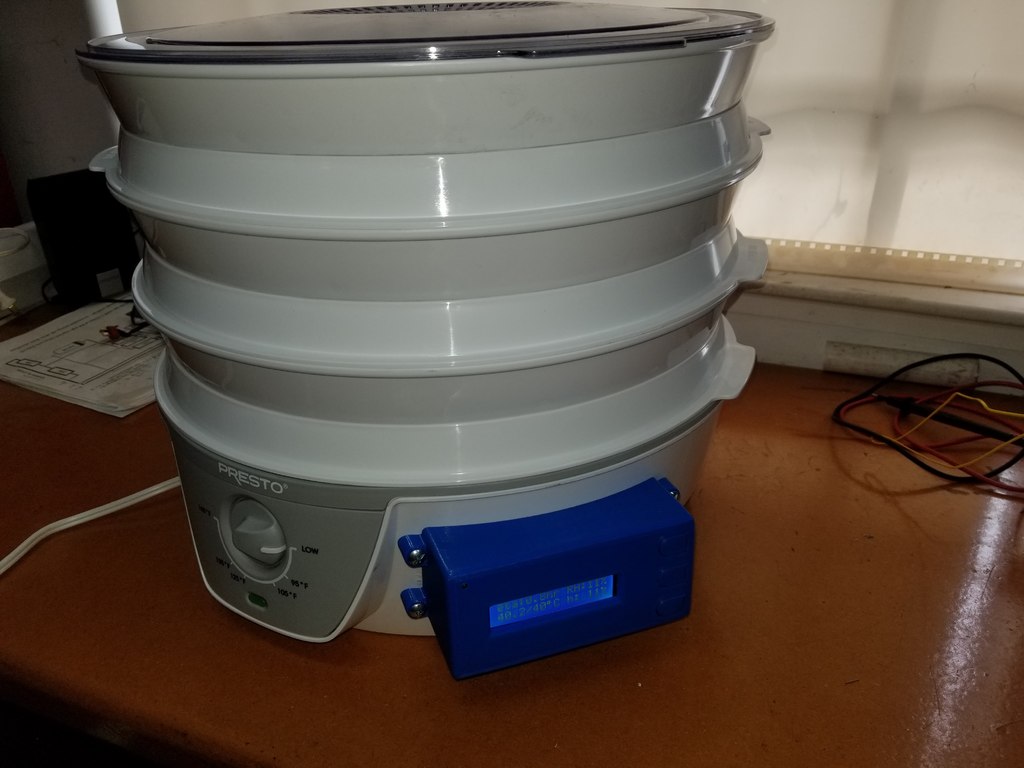
It appears you're sharing a detailed project log for modifying a dehydrator to add temperature control and automation using an Arduino board. The modifications involve adding relays, a sensor, a 5V power supply, and a user interface with buttons. The goal is to create a more efficient and easy-to-use dehydration process. Here are the main points from your project log: 1. **Adding Temperature Control:** - Installed a temperature sensor (DS18B20) in the dehydrator's heating element compartment. - Routed the sensor wire through a grommet on the base for protection. 2. **Power Supply:** - Used an old 5V Bluetooth headset charger as the power supply for the Arduino. - Soldered THHN 14awg wiring to the wallwart's outlet prongs and fed it through the relay box hole to connect it to line voltage. - The 5V line passes through the relay box and into the controller box, where it's soldered to a 5V bus board. 3. **Wiring:** - Determined what stock wiring needed to be connected where based on notes made during the project. - Used wire nuts to secure THHN near the plug cord strain relief and electrical tape with zipties for additional security. 4. **Updates and Fixes:** - Version 2 of the Arduino code shortened the button delay from 4 seconds to 1 second, kept the fan on during drying mode, and added a bigger 5V line ripple capacitor. - Version 3 removed the button delay and added an off mode. It follows a cycle of OFF - Filament Select - Dry - Holding - OFF... - Added 4k7 pullup resistors due to phantom button presses caused by induced spikes when the motor turns off in holding mode. - Updated STL files for the relay box and lid with correct printing orientations and no rectangular window that could be used to pry into the relays. 5. **Other Changes:** - Redesigned the control part with a 2-piece button mount design, which prints more easily and allows for smooth button operation without requiring hardware. - Added an RC snubber in parallel to the motor lines (0.1uF+120ohm) to absorb transients caused by the fan relay turning off and cure phantom button press events reliably. This project showcases a detailed approach to modifying existing appliances with automation technology, ensuring efficient and safe operation.
With this file you will be able to print Presto Dehydrator Control Kit with your 3D printer. Click on the button and save the file on your computer to work, edit or customize your design. You can also find more 3D designs for printers on Presto Dehydrator Control Kit.