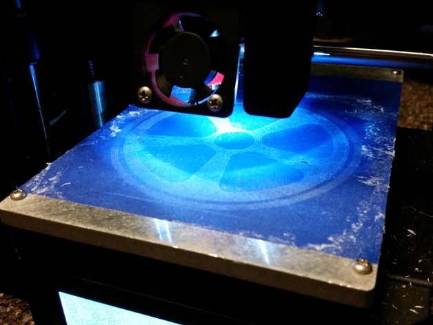
Printrbot Play LED Light
thingiverse
An LED assembly that fits inside the stock print head to illuminate the print head and the print area. The assembly contains two 5mm bright white LEDs, and is powered using the I2C header on the printrboard. Note: I can't take apart my Printrbot right now to take pictures of the actual mount since I'm missing my allen keys. I should be able to post better instructions within a week or so. Hopefully, I will also have images up as well. The instructions as they are a little too long anyway, and images will help cut down on the verbosity. Post-Printing Bill of Materials Materials 1x Printed LED Assembly 2x 5mm LEDs 2x Current Limiting Resistors 1x 4pin 0.1" Polarized Female Header 2x Female Pins for Polarized Header 3ft of Two Wire Cable 2x 2pin 0.1" Headers 2x Female Pins 2x Male Pins Tools Wire Cutters Soldering Iron and Solder Pliers Step 1a: Assemble Wire Headers Measure out the length of cable needed to string it along with the other cables up to printer head. The end should match up with the fan headers. Solder the polarized pins to the ends of this cable, and insert them into 4pin header. Make sure that when the header is inserted into the Printrboard, the cable will plug into the two rightmost pins as indicated in the following diagram. The polarity of these two pins are not important yet. Step 1b: Break Headers You may wish to add in a break header on the cable near the printer head to allow the shroud to be removed without removing the entire LED assembly. This is not technically necessary, but I would highly recommend adding these break headers anyway. Cut another length of cable that goes from the bottom of the shroud, to the fan headers in the back of the print head. Solder the non-polarized pins male pins to one of these cables, and the female pins to the other. After pushing these pins into the 2 pin housings, make sure that they connect properly. Step 2: LED Assembly Cut down one of the legs on both LEDs to about 8mm or so. It doesn't technically matter which leg is cut short, but make sure you cut the same leg on each LED. We will be checking the polarization later. Now cut one leg on each resistor to match. Finally, solder the short legs of the resistors to the short legs of the LEDs. Cut the exposed legs on both LEDs and resistors to around 8mm and test fit them in the assembly. Push the LEDs into their slots and bend the legs so that they point towards the loop on their respective sides. Now cut a length of wire that will go through the trench on the top of the assembly and connect the two LEDs in parallel. Strip the ends and solder ONE of the LEDs to this short length of wire. Then take the long cable from step 1, and tie the exposed ends to the exposed wires on the short cable. Make sure that the LED turns on when plugged into the I2C port. It it doesn't turn on, switch the two exposed wires and try again. Once you are sure that it works, solder the twisted ends to the second LED and resistor. Make sure that both resistors are connected to the same wire. It may take some fiddling to get the LEDs and resistors to fit inside the assembly. Step 3: Installation Remove the shroud from the Printrbot Play, making sure to unplug the fans. Remove the bottom fan, and press the assembly up against the top fan. Reinstall the bottom fan, sandwiching the assembly between the two fans. Reinstall the shroud and plug the fans back in. Now whether or not you decided to make the break cables, you will have to either remove the zip ties from the cable sheaths, or use more zip ties to attach your new cable to the outside of it.
With this file you will be able to print Printrbot Play LED Light with your 3D printer. Click on the button and save the file on your computer to work, edit or customize your design. You can also find more 3D designs for printers on Printrbot Play LED Light.
