printrbot to normal reprap electronics mod and printable connector fittings
thingiverse
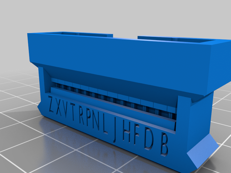
note: that resin shrinkage over time is different depending on type of resin, for example the orange resin i use needs to be scaled 101%. shrinkage happens over time and it will make parts hard to remove or crack if not oversized. but different resin types have different shrinkages, so 100.5-102% scale should allow part to still fit from resin printer. if not properly scaled it still will work, but it reduces life on the bigger 26pin cable connector, and it can crack over time if not scaled according to the shrinkage of resin. I might also update parts with a 101% scale in the future. uploaded a 13x13_2_54_connectorv6thickerW_labelled_fixed.stl file that has been fixed from netfabb online services tool. cura sliced it correctly but sla slicer had issues unless post processed and fixed. this design has been used to modify several printrbot metal pro's so far and the instructions are improving and will be added to this soon. 50-100ohm resistors are important on j i wires and H wire that needs to go to y endstop. all connectors are labeled, and the resistors prevent damaging if mis wired. M wire goes to vcc 5v, which happens to be center pin on f5, f6 series boards. check pinout descriptions if using other versions of reprap boards. also a f5, f6 drilling jig is included to drill hole for f5, f6 board placement. this board also has regular usb connector. jig designed by Joshua Hjelmberg streamlab97351@gmail.com there are two instruction manuals being added. 1 is make_replacement_cable.pdf and printrbot_to_new_board_connection_setup_guidev2.pdf it does have some edits that still need to be done, but it is usable. it will be updated again. *note i have built it locking mechanisms for pins. these are fine detailed, and normally require a resin printer, however i have modified the locking mechanisms in versions with a "w" at end of file name for wide single pin locking mechanism these should print on a fdm with 0.3mm nozzle but also might need to be mesh mixed to work with fdm as the designs are optimized for resin and the aliasing done during processing i have re-uploaded the daughter board side ide connector plastic print part because the right side pin for polarity was off by 1.3mm. this is now fixed. some parts will be updated with lettering to make verification and hookup easier. for example y pin headers state which axis they hook up for and 2 pin wires indicate therm and fan1 or fan2 or heat (if not there it still is in process). after parts are all remade labelled work will go into verifying diagram on reprap page. https://reprap.org/mediawiki/images/2/29/Printrbotupgradekitwithprintableparts.png and end connector of 26 pin shown up close https://reprap.org/mediawiki/images/5/5c/Printrbotupgradekitwithprintablepartsside.jpg and other side here https://reprap.org/mediawiki/images/f/f1/IMG_7954.JPG This is a result of a project i'm volunteering for weekly one evening a week on at a maker space and stem lab for kids. the parts here are what is used to replace the printrbot metal pro cable management from the upper assembly and allows for the attachment to go to regular reprap boards, that are either printrbot f4,f5, or ramps or whatever. the goal is to not only make these pins, but to label the sub connectors with the corresponding letter to connect to the printed 26 pin connector. the idea is to reduce error rate dramatically from hook up and wiring, and reduce knowledge and time and skill required to make such a change. also make the kit as cheap as possible. in my case there are about 15-20 machines in various states of needed repair. the hardware will last 10-15yrs but the electronics is already worn out. this is a collection of the files used to make the various parts as well as some of the blender files for boolean removal or placement of lettering. also the openscad files are included. part of the setup requires an 18 inch ide 26 pin 2 side male cable, and then hobby connector pins 2.54mm, remove the plastic sleeves and insert the male end into the 26 pin printable header, and the female end into the sub connectors. i'm changing the sub pin headers to be labeled like the 26 pin header is so wiring will be easier, also the sub headers will have indicators ether in text or graphics as to there placement, also some connectors are polarized. and wiring for 3 pin limit switches will include a 100ohm resistor in design specifications to avoid damage from hooking up incorrectly during testing the link to wiring is still being worked on but it can be found in reprap here https://reprap.org/wiki/PrintrbotMetalSimpleDaughterboardtoControllerCable well thought out feedback much appreciated
With this file you will be able to print printrbot to normal reprap electronics mod and printable connector fittings with your 3D printer. Click on the button and save the file on your computer to work, edit or customize your design. You can also find more 3D designs for printers on printrbot to normal reprap electronics mod and printable connector fittings.