Promega Metrol Probe Slide Mount
thingiverse
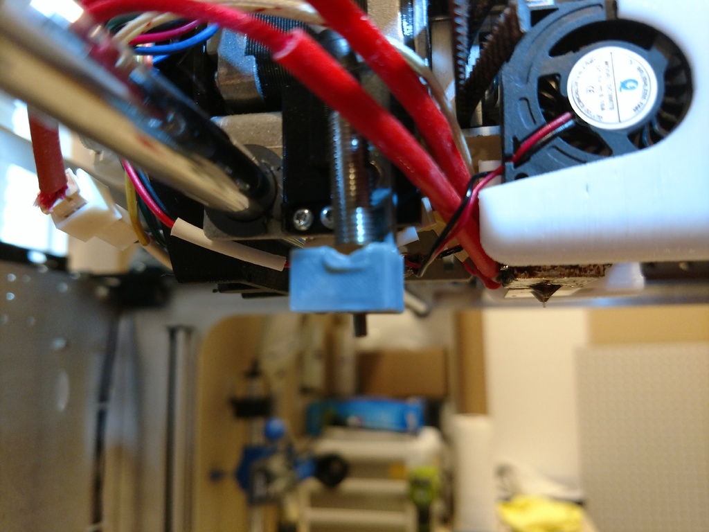
This is a printable mount for an M6 threaded Metrol Probe designed for use on the M3D Promega. The original files and mount designs were developed and distributed by M3D and held a pressure activated micro switch for bed leveling and meshing. I'd also like to give a shout out to user leonmf for his original mount redesign, and DMCShep for his assistance with wiring. As well as a special thanks to M3D and their employees for their open source and adaptable design in the first place! I also posted their original Slider Housing file to have them all in one place. It has been unchanged from M3Ds version and you can print and replace JUST the slider if need be. **BOTH Slider files will need to be scaled 10% in all directions within your slicer before printing!** --- To make this Modification you'll need the following: Metrol Positioning Switch, M6x0.75 Threaded, NO Type, CS067A Link: http://a.co/d/3GDDAC6 My Metrol probe came with two M6 nuts, as well as plenty of cable, but be sure to pick up a handful of M6 nuts and bolts if you don't have any (in case of insert failure). You could also use a brass M6 nutsert if you were so inclined, but it must not be taller than 8mm! Also, order a healthy number of 5mmx3mm Disc neodymium magnets, such as these: 5mmX3mm 70pcs Round Magnets Link: http://a.co/d/92mMSIp If you don't already have a set of Dupont pins, getting a set and a proper Crimper/Stripper isn't a bad idea either: Dupont Pins (assorted) Link: http://a.co/d/g9SHptc --- The first step of the project is to print and assemble the mount and slider. If you opt to use the existing mount, you can skip printing a new one. Be sure to pay attention to how you orient both the slider and its housing on the bed - compare to the one that came with your Promega! There are two "Slider" files that both work with the housing bracket, both need to be scaled to 10% in all directions: The first is "Metrol_Probe_Slider.stl" - it is designed to have a 6.5mm hole. If you print it upright, I've found the M6 threaded metrol probe will thread onto the bottom layer w/o needing an insert (this is based on leonmf's hole dimensions). It is not as sturdy as the version with the M6 nut added and may require glue or an additional spacer of some sort (perhaps a few wounds of thread seal tape to get a snug fit). The second is "Metrol_Probe_Slider_M6NutInsertV3.stl" - it is designed to have a 7.5mm hole with a chamfered top. This is best printed with its back flat on the bed. The hole is just slightly smaller than the 8mm wide M6 nut, so be mindful of extra plastic bunching, blocking or even seeping into the bottom side of the nuts threads. Having the proper 6mm cylinder solder tip can help with this (or use a lighter to heat up the nut while an M6 bolt is in the nut, which can also prevent plastic from curling inside the nut and seeping into/blocking the threads). Once you've chosen your slider (and inserted the threaded nut or nutsert), use a flathead screwdriver to position your magnets CORRECTLY (be mindful of attraction/repulsion) and push them into the printed holes. You can use superglue or elmers glue to affix them in place, mine fit snugly enough on their own. If you do, be sure to use it sparingly and not create raised bumps or lips that would prevent the slider from moving up or down. After, verify that the pieces fit and slide between the two positions, pay special attention to make sure when the slider is in the "down" position it does not wiggle or travel upwards. It should, just like the original, remain firm until a substantial amount of pressure and then retract completely into the "up" position. Set that aside for a moment and grab your probe. Measure the length of cable attached and trim or extend it as needed. Mine was too long, but I just wound up the extra and taped it out of the way of the board, power supply and cable chain. My probe had two wires - Blue (neutral or ground) and brown (live or hot) - once trimmed to length, go ahead and crimp female Dupont pin receivers onto the ends of the wires. I recommend you use single female plugs for both wires (picture above), so you can easily place them on the right pins (E0 Endstop pins on the Duet 2 Maestro; blue to GND, brown to E0 STOP). Now that your probe and mount are prepared, carefully make sure the Probe threads onto your Slider and position it so that the probe portion sticks out several millimeters (3-5, as pictured above in the photo with the mount attached and in the "down" position). Attach the mount and slider to your printer using the tiny OEM screws and nuts. Now you are prepared to feed the Metrol wire through the Promega's cable chain. Once completed, refer to the Duet 2 Maestro wiring Diagram (and the image above) to find the correct pins. Wiring Diagram for Duet 2 Maestro Board: https://duet3d.dozuki.com/Wiki/Duet_2_Maestro_Wiring_Diagram **Ensure power is OFF to the printer before any modifications! Discharge static electricity safely, unhook ethernet and power cables to be safe when working with the board! Better safe than sorry!** You'll need to unplug the two black wires that led to the old switch (remove them from the cable chain or not, your decision - I clipped off the broken micro switch and left the two wires in the chain in case I want to use them in the future). Once those are removed and out of the way, carefully slide the new connectors onto the pins. Ensure Ground (blue or black) goes to Ground and the other wire (brown in this case) is plugged into "E0 STOP" on the E0 set of pins. Verify w/ the diagram and then tuck, tape or zip tie excess cabling out of the way. Now plug your printer back in and turn it on. Seeing as the mount is nearly in the same exact place as the previous micro switch - you shouldn't need to measure the X, Y tool head offset (unless you want 100% positional accuracy with the probe), but you WILL absolutely need to re-calibrate the Z-Offset before use. You can do this by following instructions in the getting started guide or by running Macro #1 - Calibrate_Z_Probe. From there, pat yourself on the back - you can calibrate and mesh the bed as you would do normally, but now its done with improved accuracy and w/o worries over a thin armature breaking off. Cheers! --- Comments, improvements, suggestions most welcome!
With this file you will be able to print Promega Metrol Probe Slide Mount with your 3D printer. Click on the button and save the file on your computer to work, edit or customize your design. You can also find more 3D designs for printers on Promega Metrol Probe Slide Mount.