ProperWinder - Filawinder kit upgrade
thingiverse
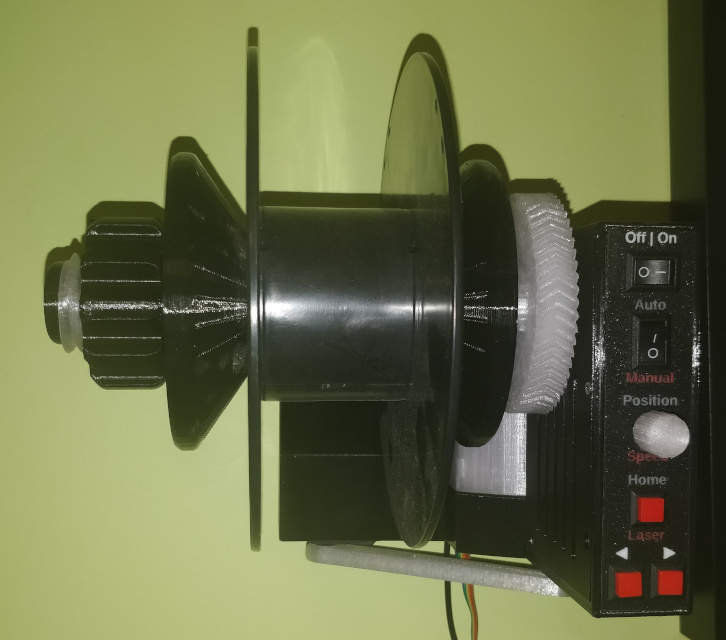
Note: Updated on March 4, 2021 with a new motor tray and double gear that uses 625ZZ 5mmX16mmX5mm bearings. When I put together the laser cut acrylic filawinder kit that I bought in early 2020, I thought two things. 1. This is very flimsy and frustrating to use, but the concept is pretty sound. 2. We can rebuild him, we have the technology. This is a complete frame replacement for that kit. The motor, control panel components, threaded rods and nuts, control board, and magnet are all reused. Additional components needed are as follows: * A 5.5mm x 2.1mm DC Power Extension Cable (Right Angle Male to Female adapter) or equivalent. This is necessary as there is not enough space to plug the original adapter into the board when mounted inside this unit. The [one I used](https://www.amazon.ca/gp/product/B0827V3MXM/ref=ppx_yo_dt_b_search_asin_title?ie=UTF8&psc=1) was 10" long. * 2pc M3X6 set / grub screw * 5pc M3X3 machine screws * 1pc M3X8 * 15pc M3X10 * 1pc M3X15 * 25pc M3X3mm X 4.2mm OD threaded heat-set inserts * 2pc PC4-M10 passthrough pneumatic connectors (to secure PTFE coil) If using V1 of the motor tray and double gear * 1pc M3X30 machine screw If using V2 of the motor tray and double gear (recommended) * 2pc 625ZZ 5mm ID X 16mm OD X 5mm thick bearings * 1pc 5mm round steel rod cut to 58mm Key Features: * Internally mounted motor * No tools needed to mount or remove spools * Sturdier construction allows elimination of secondary support arm * Multiple hanging options (the original design had a distinct lack of mounting holes) * Compact design optimized for printing without supports / large nozzle sizes. * optional faceplate with color coded labels (MMU / multi extruder ready) * PTFE coil (to straighten the hot filament) from original design is now its own component to allow for a more optimized filament path, also includes depth adjustment. Makes use of PC4-M10 passthrough fittings to ensure that the PTFE tubing is held more securely. Please note that the wiring access cover STL provided is a blank. I am not using it at all currently, but added it too in case anyone would like to source proper panel mounted connectors and modify this cover for that purpose. Intended for use with [Filawinder improved wall mounted sensor](https://www.thingiverse.com/thing:4199247) With gratitude to Greg Gaub for helping to test and improve this design. Please note that some components are designed with sacrificial membranes over round holes in order to eliminate the need for supports. These should be cut away before assembly. **Important note:** The connector for the potentiometer knob should be mounted upside down when attached to the control board (vs the original assembly instructions). If you don't do this, the servo arm will move in the opposite direction you expect when you calibrate it (this may be fixed in a future firmware modification, but for simplicity's sake flipping the connector does work) **Assembly steps for winder** 1. Fix heat set inserts into holes for the board standoffs and cover mounts on the lower chassis. 2. Fix heat set inserts into the holes for the joint between the upper and lower chassis. These should be installed on the non-wall facing side of the chassis to make them harder to pull through. 3. Mount the servo to the upper chassis with the servo horn on the outside edge. Thread the servo wires through the provided channel so that they can reach the control box. 4. Mount the winder motor in the motor tray and secure in place with m3 screws. Mount the drive gear onto the motor shaft and secure in place with M3 grub screws. If using the V1.01 double gear and V1.01 motor tray, Mount the double gear with the M3X30 machine screw and heat set insert. If using the bearing version of the double gear and motor tray, mount a 625ZZ bearing into each end of the double gear (a vise can be helpful here). Use 5mm round bar (cut to 58mm) as the axle for the double gear. 5. Slide the motor tray into the lower chassis, taking care not to pinch the motor wires. Fish the motor wires into the control box. Secure the the motor tray to the chassis with M3 screws. 6. Run the ribbon cable for the laser sensor from the control box through the channel with the motor wires and out the other side. Do the same with the 90 degree power cable extension. 7. Attach the upper chassis to the lower chassis from the back with M3 X 10 and M3X15 screws. There should be 2 wires hanging out of the access slot at the bottom - the ribbon cable for the laser sensor, and the female end of the power extension cable. 8. Attach faceplate, then mount toggle switches, potentiometer. The wires can be shortened or bundled up - there is enough space for the original length to be used. Take care to observe that the orientation of the toggle switches (especially the mode switch) corresponds to the printed labels. 9. Connect cables to control board, then mount control board to the standoffs in the control box. The board is to be mounted with the microcontroller facing inward and the hall effect sensor facing the axle shaft. Secure the control board cover with M3 screws. Make sure the screw heads are flush with the cover so that the magnet holder can clear them when it is installed. 10. Mount the axle bearings inside the holes in each end of the main axle. 11. Insert magnet into the magnet holder, following polarity instructions per filastruder assembly manual. The magnet should be secured in a position as close to the tip of the holder as possible. 12. Thread the magnet holder into the mounting hole on the main axle gear. The height of the magnet should be adjusted so that it comes as close to the hall effect sensor as possible. 13. Assembling the axle is slightly challenging if you do it in the wrong order. First, mesh the teeth of the main axle gear with the double gear, and push the metal threaded rod through the hole in the lower chassis and all the way through the main axle. Secure at both ends with washers and nuts from the filastruder kit. 14. There are printable plugs included to dress the holes at each end of the axle. 15. Attach the servo arm to the servo horn. 16. Assemble the two halves of the PTFE carrier by sliding them together. The holes in the top section are designed for PC4-M10 passthrough connectors. The preferred distance from the wall can be locked in place with a M3 screw in the holes on the bottom of the lower portion of this unit. 17. To mount a spool, thread a conical spool holder onto the shaft with the narrow end facing the spool. Then slide the spool over a shaft, followed by another spool holder with the narrow end also facing the spool. Tighten the second spool holder until it grips the spool. Next, lock the spool holder onto the shaft by threading the locknut STL onto the shaft and tightening it until everything is secure.
With this file you will be able to print ProperWinder - Filawinder kit upgrade with your 3D printer. Click on the button and save the file on your computer to work, edit or customize your design. You can also find more 3D designs for printers on ProperWinder - Filawinder kit upgrade.