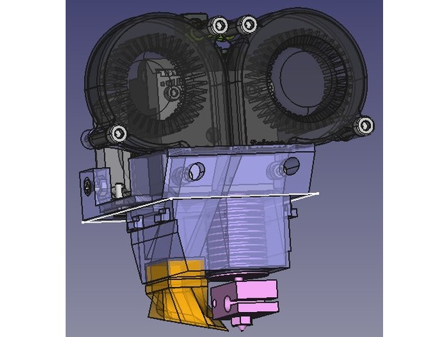
Protohead V7 "Zeus" - E3D v6 Full + E3D Titan for FABtotum
thingiverse
UPDATE 9/2/2018: I have printed this reworked version and it works great. This time I have printed it in PETG (my original was PLA). It feels way stronger and more beautiful. Still to see how durable it is. PREVIOUS UPDATE: The design has been reworked to fix the original flaws. Still untested as my PLA original is working just fine and I have no motivation to print the reworked version. Full FreeCAD source is attached so that you can customize it as you wish. At this moment, the original head is well tested. Printing awesome in ABS, ABS+, PLA so far. The result is amazing (thanks to e3d obviously, not that I did anything special). Some videos printing a calibration cube: Some simple videos: PLA:https://youtu.be/oiGCqU7qlkYhttps://youtu.be/QDAGHRTxxmk ABS:https://youtu.be/dO7hqFu-qFIhttps://youtu.be/UxlTan-TjxE After having tried several low-cost hotends and extruders and learning their weaknesses, I want to be able to see what more reputed (and expensive) components can offer. A main design limitation that is not per se a design flaw (it is intended), is that you will lose some printing area on the rear part. I just did not want to raise the titan and make it "extremely short bowden style". I wanted to use the Titan+e3dv6 as a single block. If anybody interested, you may just raise the titan a couple of cm and the stepper will go over the rear (or front if you want further redesign) part of the FABtotum. Choosing the components: I have the e3d v6 full original and the e3d titan original. Blowers: Not all the 5015 blowers are the SAME. a) Check your voltage. The fabtotum carriage blower fan is 5V. Unless you want to constantly have it activated, you need a 5V or skills to make a small PCB with a MOSFET to operate control the 24V in the head with the 5V blower fan as input. There is no 12V in the FAB head. b) Current. There are different currents for the same voltage. Higher voltage generally means more air flow and/or air pressure. In general go for the higher current ones. It shall be noted that higher voltage blowers (and within the voltage those with higher current) generally have better performance than lower voltage blowers. The blower used for cooling down the heatsink can operate at 5V (head has 5V) or at 24V (remember to enable the mill motor line in your gcode). Printing tips: Support is needed for the HEAD and the Blower conduct. Building tips: Triple read the instructions:https://wiki.e3d-online.com/wiki/Titan_Assemblyhttps://wiki.e3d-online.com/wiki/E3D-v6_Assembly Yes, please, read until the end. Yes, read the troubleshooting guides. My favorite is the "click when retraction" issue with Titan. If you do not get the meshing right, you WILL HAVE to disassemble the whole thing apart including the blowers and including any seal with thermal glue you might have made. Use the longer supplied M3 titan bolts in the bottom part. You need a 35 mm for the left (of the viewer when looking front side) and a 30 mm for the right (standard titan mounting is 30 mm for left and 25 mm for right). Seal the around the blowers input with thermal glue or any other sealant you like. Do this BEFORE mounting the titan, otherwise you will have to remove the titan later to seal the rear part of the blowers (the part closer to the titan). You might want to put some drop of thermal glue in the rear part attaching the NEMA to the v7 head (you do not actually need to reinforce this a lot, as in operation it lies on the head holder part of the carriage). The front titan supporting holes must be sealed before use, so that the air does not flow out that way. For the prototype I have just put some thermal glue. To mount the hotend, insert first the hotend from above without the heater block. Then follow e3d full instructions from their wiki, except that you have to leave the assembly of the thermistor and heater cartridges for the end. This head is compatible with the protohead PCBs, original and 24V version:https://github.com/imarin2/Protohead_PCB_v4_FAB_24Vhttps://github.com/imarin2/ProtoHead_v4 It is designed so that you thread the blower supporting holes (4 holes, 2 on the head structure and 2 on the blower joining part) with an M4 thread. Print Settings Printer: FABtotum with Protohead v6 Supports: Yes Infill: I use slic3rs 3D honeycomb Notes: For the head you need support. For the blower conduct you may need support (I used it). For the blower connector and NEMA spacers you do not need support. If you are using slic3r and you want to use "pillars" kind of support, check in the 3D view that no islands are being created:https://github.com/alexrj/Slic3r/issues/2949#issuecomment-287581663 Because of this, I used rectilinear support for my print. It has a lot of support material, check that you have enough filament in your spool ;) Post-Printing Step 1: Buy the parts Titan and full v6 hotend It takes a while to have it delivered. Royal airmail sometimes delays the delivery and it can take two weeks within Europe (it was my case). You do not need the titan 3d printed bracket. In principle you do not need the bowden parts, unless you plan to do more experiments with it. I bought the stepper from them. It is a good stepper. I bought a 0.4 mm nozzle and a 0.8 mm nozzle (Yes I want to try layers of 0.5 mm). If you anticipate your needs, you can save additional shipping costs. Blowers Not all the 5015 blowers are the SAME. a) Check your voltage. The fabtotum carriage blower fan is 5V. Unless you want to constantly have it activated, you need a 5V or skills to make a small PCB with a MOSFET to operate control the 24V in the head with the 5V blower fan as input. There is no 12V in the FAB head. b) Current. There are different currents for the same voltage. Higher voltage generally means more air flow and/or air pressure. In general go for the higher current ones. It shall be noted that higher voltage blowers (and within the voltage those with higher current) generally have better performance than lower voltage blowers. The blower used for cooling down the heatsink can operate at 5V (head has 5V) or at 24V (remember to enable the mill motor line in your gcode). Here you probably should first decide how do you want to connect your head to the FABtotum. Options are: Prototype option My prototype does not use the fabtotum head connector. It takes 24V from the power supply to continuously run two 24V high CFM blowers. It uses therm1 connector for the thermistor and has a extruder cable soldered in the totumduino that goes to the head (there is a connector in the middle). The 4th axis is also directly cabled to the head. You may find this information relevant if you choose this option:https://github.com/Opentotum/Opentotum/wiki/totumduino-solder-points Variant 1 The design supports a 24V PCB for protohead (that I previously released with Protohead v6). This way you can get the signals form the head connector. Variant 1a : Just connect two 24V blowers to the milling motor and activate it via gcode and it works like the prototype above. Variant 1b: You use a 5V blower for the part cooling and enable the “milling motor” 24V lines via GCode to enable the heatsink cooling blower. In this variant you still need to bring the 4 axis as cables to the head. You may reuse the 5V blower of a FABtotum head if available. The thermistor and extruder you can also connect it to the PCB. The PCB: https://github.com/imarin2/Protohead_PCB_v4_FAB_24V Variant 2 It should be possible to use the servo pins for dir/step a driver mounted on the head. I have got this idea for another FABtotum forum member, so I do not take any credit for it. Apparently FABtotum PRO head uses this and is support by the latest FABlin, so it should be possible to use the latest FABlin. I have no interest currently on variants 1 and 2, as my flex cable is broken enough to need to cable extruder and thermistor to the head, and then, well, I do not care to just cable everything. Footnotes on blowers: The best 24V is substantially better than the best 5V I have found. The 5V fan (blower) on the flex cable is current limited (original flex, original totumduino, not taking about core or totumduino v2), so even if you put the best 5V blower (the one in the FABtotum hybrid head is acceptable/good), you may have limited performance. Some resellers cheat with the stickers they put on the products. Some 24 V 0.14A blowers actually are 24V 0.06A blowers. You can check this with a multimeter or regulated power supply with current indicators. Bolts and nuts You only need four M4 x 25 mm bolts for the head. The attach to the plastic once you thread it with an appropriate threading tool. If you choose to use the PCB, then you need 2 short (8 mm? shorter? custom cut? You will discover the limitations when you try to put the stepper on the PCB) M3 bolts and 2 M3 nuts. In principle, you do not need the two M3 bolts and nuts provided on the rear part to attach the NEMA stepper. Step 2: Remove support From the head part: It is going to take you maybe 1 hour to remove all the support without damaging the head part. When you think you are finished, try the structure on the FABtotum carriage for dimensions and tweak the flaps that form the mechanical connection until it fits without issues. Take special care with the blower supporting structures (read the design flaws above). Thread the blower supporting holes on the head and on the blower joint (4 holes). From the blower conduct: It is going to take you 10 minutes, take care not to break the walls when removing all the internal support. Step 3: Mount titan and e3d Mount Titan:https://wiki.e3d-online.com/wiki/Titan_Assembly Mount v6:https://wiki.e3d-online.com/wiki/E3D-v6_Assembly In the v6: Do not put the conductive paste at this time and do not mount neither the thermistor cartridge nor the heater cartridge, but do familiarize with the steps involved. In Titan: You have to mount everything using the standard bolts and the NEMA spacer. Make sure you do not have backslash (refer to the "clicking sound during retraction" section in the assembly guide). Yes you will change those bottom bolts (with the other e3d supplied ones), but not at this time. Step 4: Mount and seal the blowers So easy, mount the blowers in place and seal the air inlet (for example with thermal glue). Do not close the front bolt holes at this time. Step 5: Mount a partial titan-v6 assembly in onto the head Remove the heater block and heat break from the heatsink (that is why it was important not to mount the cartridges). Remove the bottom two M3 bolts from the titan (make sure the top left bolt is tight or the titan assembly will move and you might have backslash later). Mount the titan+heatsink into the Zeus v7 protohead. When in place, use the M3 bolt that was bottom left (your left in a front view) for the bottom right (in other words put the 30mm long one in the left part where the 25 mm long one was previously in place). Take one of the extra 35mm long M3 bolts supplied by e3d for the bottom left one (you do not need the 25 mm one anymore). Tight well the bottom left M3 and the right left as provided by the titan assembly instructions. Now test that you do not have backslash in Titan. Step 6: Mount the heater block on to the heatsink Now apply the thermal conductive paste on to the heatbreak thread as in the e3d v6 instructions and insert the heater block with the nozzle and heat break into the heatsink as per e3d v6 instructions. Step 7: Mount extruder and thermistor cartridges Now you have to put the heated block handtight in the right orientation. Realize that at this time you can always reorient the block. However after installing the cartridges you won't be able to (as you can not grip the heatsink anymore). Take special care not to move the assembly when installing the cartridges or when heating to 285ºC (or 275ºC if the FABtotum firmware refuses to heat more) to tight the nozzle to the heatbreak. Insert the thermistor cartridge from above. The connector will be between the stepper and the head structure. Note that there is one orientation where slightly more cable can go in. This is important as the cable is just the minimum required size so that the cartridge enters in place. Connect the thermistor to the heating block as per e3d instructions. Insert the heater cartridge cables from beneath and out at the same place the thermistor connector is. Install the cartridge in the heating block as per e3d instructions. All the sleeves of the cables should go up via the hole until it is no more than the necessary amount of cable. This should prevent interference with the z probe (if it does not, deactivate the z probe in FABUI, as it is a worthless feature for homing, better to just calculate the Z max and insert the value in FABUI. I do not use the zprobe anymore). Step 8: Mount the new head in place in the carriage and connect the cables (if needed) Here the connection depends on whether you are doing direct connections, the PCB... I use a PTFE tube up to the spooler and put all the cables around the PTFE tube and fix them with tape. Configure FABUI: a. Insert the NEMA steps as per e3d instructions in the extruder calibration in either settings or maintenance (I can not remember and nevertheless it might change). b. (optional?) Deactivate Zprobe and put the length. For this go to jog, run G27. Get the Z with M114 (Z1). Then jog up the bed until it just touches the e3d nozzle. Get the Z with M114 (Z2). The value is Z1-Z2. c. Put homing to the right (at least this flawed design can not work with left homing, the head will prevent the carriage x endstop from reaching the designated area) d. Select a Print v2 head in FABUI (or you will hit a critical temperature problem passing 235ºC) e. Custom configuration: M801 S296 M800 S4 M804 S0 M301 P15.57 I0.84 D72.45 Note: The last one is the PID configuration and is quite bad as it has not yet been calculated for this head. Configure FABlin: You need to modify FABlin and include these in "Marlin/Configuration.h" +#define THERMISTOR_HOTSWAP_SUPPORTED_TYPES ( 170, 11, 1, 171, 5 ) +#define THERMISTOR_HOTSWAP_SUPPORTED_TYPES_LEN 5 +#define THERMISTOR_HOTSWAP_DEFAULT_INDEX 4 // the index of within the supported types to which the printer will be initialised. You need a recent Arduino IDE for compiling it. For flashing refer to to these guidelines:https://github.com/Opentotum/Opentotum/wiki/force-totumduino-flashing Go to JOG and try to move the stepper. Check the sense of rotation. If it is inverted you have to change one phase of the cabling (Google is your friend). Step 9: Tighten the nozzle and seal the front bolt holes Disable the part fan (without the silicon socket it is difficult to heat the block with the part blower on) Put the extruder at 270º-275ºC With great care not to misorient the heater block tighten the nozzle (remember the force you have to apply is one finger strength only). Extruder to 0ºC, wait for cooling and mount the silicon socket. Connect the part blower. Seal both front holes (only superficially) for example with thermal glue. Step 10: Configure retraction in your slic3r and upload a calibration cube Retraction: 0.5 mm is enough for me so far (e3d recommends 0.5 mm ABS, 0.8 mm for PLA, around 2mm for very flexible materials). I hope did not forget anything. How I Designed This FreeCAD v.17 - ubuntu daily build Mainly Part Design NEXT with reference planes for robust design (no importing of external geometry in the sketcher). Draft WB for positioning. Fastener WB for well, fasteners (bolts, nuts). Thanks to all that make FreeCAD possible. You are great!
With this file you will be able to print Protohead V7 "Zeus" - E3D v6 Full + E3D Titan for FABtotum with your 3D printer. Click on the button and save the file on your computer to work, edit or customize your design. You can also find more 3D designs for printers on Protohead V7 "Zeus" - E3D v6 Full + E3D Titan for FABtotum.