Prusa i3 MK2-X

Prusa i3 MK2-X

thingiverse

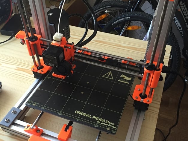
MK2-X is implementation of most of Original Prusa i3 MK2 mechanical and electrical components into metal frame from RebeliX project. The goals are: Significantly more rigid frame, which can be assembled easily and precisely. Reuse as many original parts as possible, especially all X-carriage assembly with extruder. Make basic parameters easily adjustable. Frame is built from AL profiles 30x30mm (slot width 8mm), frame couplers and steel Y-rods are original from RebeliX project. Frame dimensions are 360x380x390mm (WxDxH). Y-rods are 360mm long. Profile lengths: X: 360mm (3x) Y: 320mm (2x) Z: 330mm (2x) Linear bearings for Y-carriage are replaced by their longer version LM8LUU. You can also use two LM8UU in row instead of one LM8LUU. You can even use only one LM8UU, in that case put it in center of bearing housing. But with longer bearings the bed is significantly more stable and rigid. Top end of Z lead screws is secured in 8x22x7 bearings. You will need some M6 screws and nuts to build the frame and mount printed parts onto it, and some M2,5 screws, M3 screws and self-locking nuts to mount MK2 equipment. X-home position as well as geometry of Y-carriage can be adjusted by moving Y-rods. Y-home position can be adjusted by M2,5 screw in Y-belt-holder under the bed. Y-belt is tightened by simple belt tightener implemented in Y-idler (M2,5 screws). See also http://www.thingiverse.com/thing:1898131 - modifications made for Igus RJMP-01-08 linear bearings. Important notice: Parts not listed here (for example whole X axis) are supposed to be taken from your original Mk2 printer without any modifications. If you are building the printer from scratch, you will have to get those parts source files from Prusa's github yourself. Print Settings Printer: Prusa i3 MK2 Rafts: No Supports: No Resolution: 0.2mm, 3 perimeters, 3 bottom layers, 4 top layers Infill: ABS 15%, PETG 40% Notes: To print: 4pcs Y-rod-holder, 2pcs Z-axis-top (one mirrored around X), 2pcs Z-axis-bottom (one mirrored around X), 3pcs Y-bearing-housing, 4pcs al-profile-cover, 2pcs al-profile-cover-with-hole, 2pcs psu-mount-socket, 2pcs psu-mount-plug, all other files as one copy. Don't print from PLA. Parts touching potentially hot surfaces (motors, bed, PSU) could deform if printed from PLA. How I Designed This All parts are designed to be printed easily from ABS without supports and without significant warping. Regarding holes - usually if the hole is rounded, the screw should go easily inside, the hole might need to be finished by drill. If the hole is hexagonal, the screw is supposed to cut the thread there. Don't use drill on this type of holes. Parts are designed with exact dimensions. You may need to do necessary adjustments to fit your printer and type of filament. Some parts contain adhesion pads in corners (e.g. profile covers). They're supposed to be cut away by sharp knife. Additional info Current TODO list Redesign Y belt tightener for more comfort Maybe redesign Y-endstop mount, put Y-endstop on Y-rod-holder to avoid unreasonable dependency of Y-endstop and position of belt pulley on Y-motor. References Original Prusa i3 MK2: http://shop.prusa3d.com/en/3d-printers/59-original-prusa-i3-mk2-kit.html RebeliX project: http://reprap4u.cz/rebelix/ (Czech only) Changelog 2016-07-27 initial upload 2016-07-28 added LCD mount, new supports replace original ones and all LCD assembly then slides into front rail of the frame 2016-07-28 added Rambo mount 2016-07-28 added AL profile end cover and cover with hole (power lines from PSU to Rambo goes there) 2016-07-29 added assembly guide while still in memory ;-) 2016-07-30 temporarily remover AL profile covers (need redesign), added PSU mount socket and plug 2016-07-30 added new AL profile covers 2016-07-31 finished conversion guide, added few photos of completed printer, cleared "work in progress" flag 2016-08-31 made RebeliX build instructions permanent download link, added original RebeliX corner couplers source STL files 2016-09-17 changed orientation of y-rod-holder 2017-02-12 redesigned some parts to make them work with standard 3030 extrusion T-nuts 2017-05-09 enlarged slots for 3030 T-nuts (was 8mm, now 10mm) 2017-05-09 redesigned z-axis-top and z-axis-bottom: moved down 5mm to avoid colision of probe protector and Z-motor screw, added tightening screw to top part, added hole for adjusting screws Brief assembly (conversion) guide Assemble the frame using only AL profiles and frame couplers, refer RebeliX guide for details. It's in Czech language, but with a lot of images. You can do it. :-) You can find one at http://s000.tinyupload.com/index.php?file_id=08086742443431387385 Original file can be found at http://reprap4u.cz/navod-na-stavbu-3d-tiskarny-rebelix/ but their download link sometimes doesn't work. When assembling the frame, don't forget to slide in required amount of nuts. They will be needed later. Without them you will have to disassemble the frame to mount printed parts. Also remember that rear edge of vertical profiles should be exactly 115mm from back side of the frame as shown on page 13 of RebeliX guide. Mount Z-axis-bottom (left and right, watch the orientation), tighten. Mount Y-rod-holders, Y-idler, Y-motor-holder, don't tighten (will be adjusted). Slide LM8LUU into housings, mount on Y-carriage, don't tighten. Slide in Y-rods, snap into Y-rod-holders (adjust positions). Fix with zip-ties. Check geometry of Y-carriage (should be parallel with frame), check movement (should move freely in all way in/out), adjust rods if needed, tighten rod holders a little to prevent unwanted moving. Mount Y-motor with endstop. Tighten motor screws, not frame screw. Mount Z-motors (watch cable lengths, longer to the right), tighten. Slide X-carriage assembly on lead screws carefully. Slide in Z rods carefully and stick them in Z-axis-bottoms until they touch motor bodies. You may need to use a little force. Use M3x16 screws and square M3 nuts to assemble z-axis-top parts. Put 8x22x7 bearings into Z-axis-top parts and slide them on lead screws and Z rods (watch orientation). Tighten to the frame. Check geometry, should be perfect. Put M3x30 screws into prepared hole (see images), it will limit vertical travel of the extruder. You can use the screws later for fine-tune of X-axis level. Lay the frame on side, mount heatbed on Y-carriage, mount Y-belt-holder. Assemble Y-belt (path of belt should be straight), tighten a little using adjusting screws on Y-idler. Don't overstress Y-idler. It's a printer, not guitar. Check if Y home adjusting screw clicks Y-endstop when in home position. If not, adjust positions of belt pulley + Y-motor-holder, or heatbed. Return the frame to normal position and check the geometry of Y-carriage. Should be parallel to frame and approx. centered in X axis. Adjust by sliding rod holders in frame. Tighten. Adjust Y belt if needed. Connect cables to Rambo and check function. Both Rambo and PSU are NOT mounted to frame at this step, just laying around to check function and fine adjust geometry. Watch the cables, they shall not collide with moving parts. Check adjustment of home position - do Auto Home command. When finished, Z-probe should stay just above probing point. If not, adjust X by moving Y rods left/right (watch the Y-belt), adjust Y by adjusting screw in belt holder. Recheck home position and repeat until satisfied. === The printer should be able to work at this point. Place Rambo mount on the frame. The bottom side is where M3 holes are closer to edge. Align the height of bottom side around the height of heatbed. Don't put it too low, you won't be able to mount and close the casing door. Don't put it too high either, the cables aren't that long. In particular right Z motor cable is way too short. Mount Rambo in its casing the same way as in Original Prusa i3 MK2. Now comes the tricky part. You will need to replace power cables for longer ones. You need cables 75cm long. Remove black Prusa cover from PSU, drill a hole to bottom side so new cables can go out from bottom side on outer edge, approximately between mains socket and mains switch. Replace cables and put the cover back. Mount printed PSU-mount-plug onto the PSU, use the same screws and holes as on MK2. Slide in printed PSU-mount-sockets. Attach the PSU assembly to the frame by hand all the way down (bottom side touches frame coupler) and mark the position of sockets on Z frame profile. Remove sockets from assembly and mount them on the frame at marked positions. Slide in the PSU. Slide one AL profile cover (with hole) on both cables, put cables through rear traverse frame profile (via center hole) and fit the cover. Slide another cover on both cables on the other side and fit it on the frame. Mount connectors on cables and connect power to the Rambo board. Replace LCD supports by new ones, connect LCD cables at LCD side and then slide both supports into rail in front traverse frame profile. Fit two AL profile covers on front frame profile, another two on top frame profile. Finish cable management. I used some RebeliX cable clips combined with zip ties. Done. Feel free to make additional gadgets yourself. :-)

Download Model from thingiverse

With this file you will be able to print Prusa i3 MK2-X with your 3D printer. Click on the button and save the file on your computer to work, edit or customize your design. You can also find more 3D designs for printers on Prusa i3 MK2-X.