Prusa i3 MK3s Raspberry Pi Case with integrated 5V power supply
prusaprinters
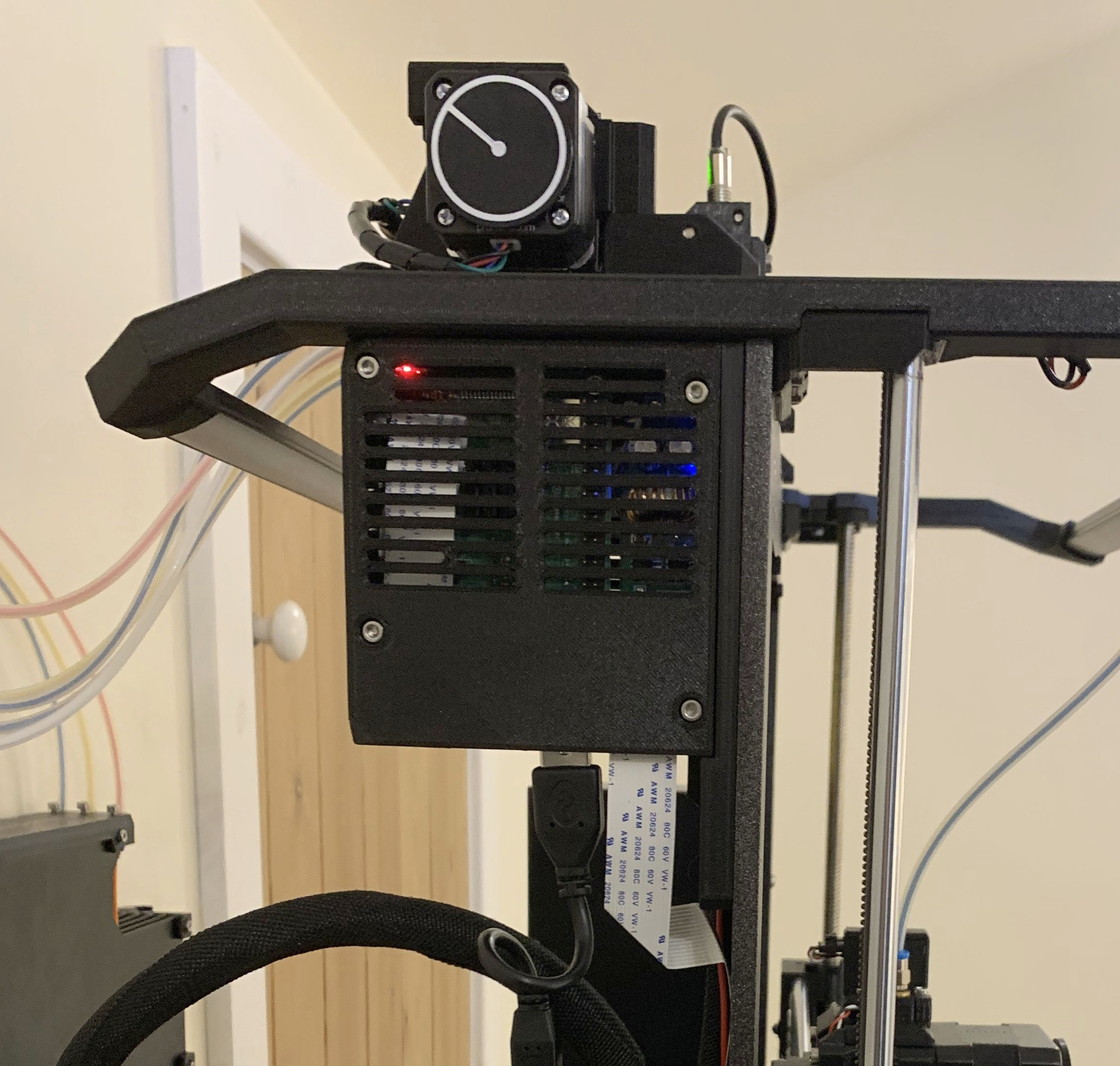
<p>One of the first things I added to my Prusa i3 was a Raspberry Pi 3B+ running the excellent OctoPrint platform as this provides WiFi remote control and webcam monitoring of the print – a must for any 3d printer.</p> <p>However, I wanted a fully integrated solution that could include the Raspberry Pi, and its power supply with on-off switch, and would be connected to the Prusa i3 MK3S’s 24V PSU so it looked like it was part of the original design rather than just a bolt-on, without extra cables and power supply trailing across the work bench.</p> <p>I also have the Prusa MMU2 and <a href="https://www.prusaprinters.org/prints/7633-mmu2-led-light-bar-prusa-i3-mk2mk3">"MMU2 LED Light Bar" by Sethbon</a>, so the case has been designed to fit around these, and provide an integrated power swich and wiring channel for the light, as well as an optional cable clip that helps manage the wiring loom to the MMU.</p> <p>This design is built from scratch (Solidworks Part files and STEP models include), but inspired by the designs of <a href="https://www.thingiverse.com/thing:3004038">agarajag</a> and <a href="https://www.thingiverse.com/thing:2334119">hackoholic</a> on Thingiverse, which I had printed and been using for a few months before this case.</p> <p><b>You will need:</b><br/> In addition to printing the design files, you will also need the following…<br/> (NB: The links are to the parts I bought and are povided for example only - I've tried to use parts that could be easily sourced from a variety of suppliers).</p> <ul> <li>Assorted <a href="https://www.amazon.co.uk/gp/product/B07QDQ2959">M3 hex cap-head screws and nuts (see drawing for quantities and sizes - x4 35mm scews, x2 20mm screws, x1 15mm screw, x4 10mm screws, x8 nuts)</a></li> <li>1 x <a href="https://thepihut.com/collections/raspberry-pi/products/raspberry-pi-3-model-b-plus">Raspberry Pi 3B+</a> (design supports additional camera module and flat-flexible-cable routing)</li> <li>1 x <a href="https://www.amazon.co.uk/gp/product/B07DNHXWV5">Adjustable DC-DC Power Supply Module, 24V In, 5V out (10A)</a></li> <li>2 x <a href="https://www.amazon.co.uk/gp/product/B08HHJPVTS">On-Off rocker switches (power and light control)</a></li> <li><a href="https://www.amazon.co.uk/gp/product/B08LNWMMHQ?pf_rd_r=CN83C5FGH9C3H1N6GN2C&pf_rd_p=6e878984-68d5-4fd2-b7b3-7bc79d9c8b60">3-way/4-way 3A terminal strip (optional)</a></li> <li>Assorted electrical wires and crimpts as required (red/black etc)</li> <li>40-way 0.1" pitch header for J8 on the Raspberry Pi (optional - I soldered the wires to the solder joints on the rear of the boards pin header).</li> </ul> <p>Plus...</p> <ul> <li>1 x <a href="https://www.amazon.co.uk/gp/product/B071YJ7LWB"> 15cm USB Cable (from Pi to Prusa)</a></li> <li>Raspbery Pi <a href="https://thepihut.com/products/raspberry-pi-camera-module">webcam</a> and <a href="https://thepihut.com/products/flex-cable-for-raspberry-pi-camera-or-display-1-meter">flat-flexible-cable</a> to length as required for your camera mount.</li> </ul> <p><b>Assembly:</b><br/> I printed both halves of the case in PETG, but PLA also works.<br/> Having inserted the switches into the case base, feed the red and black power wires (cut to be long enough to go to the main 24V power supply terminals) upwards into the case through the internal channel in the main mounting boss.</p> <p>I wired the top switch as an on-off switch for the 24V power going to the 5V power-supply module in the case, and the bottom switch as an on-off for the power going to all the lights on and around the printer.<br/> If you have the excellent "Light Bar" design by Sethbon (see link above), then power to this can be fed out of the case and up into through the internal channel.<br/> I've included some photos of my internal wiring, and you can see there is space for a few 3A terminal bocks if needed (mounted below the Ethernet/USB connectors of the Raspberry Pi).</p> <p>At this stage, before connecting the Raspberry Pi, I connected the adjustable DC-DC power supply, and set its output to 5V, using a voltmeter to check this. I then soldered the 5V output wires onto the rear of the Raspberry Pi board to J8's pins 2 and 6 (see attached photos and diagams).</p> <p>The lid part has a slot in it, allowing the flat cable of the Raspberry Pi webcam to be fed in and folded at 45degree angles through various other internal slots to holding it in place before it is plugged into the Pi module.</p> <p>Both the webcam cable, and power supply cables can be routed down into, or behind, the main Prusa electronics enclosure - this can be seen in one of the photos if you look carefully.</p> <p>If you have a Prusa MMU, the inclued cable clip part can be fitte to the upright plate, after the case, to help hold the MMU cable loom neatly in place vertically.</p> <h3>Print instructions</h3><p>I printed this in PETG, but also works in PLA. Print time is about 9hrs 45mins, and uses about 90g (30.5m) of filament.</p> <p><b>Printer:</b> Prusa i3 MK3S<br/> <b>Rafts:</b> No<br/> <b>Supports:</b> Yes, but on baseplate only<br/> <b>Resolution:</b> 0.2mm<br/> <b>Infill:</b> 20%-25%<br/> <b>Perimeters:</b> 2 to 3</p> <p>After printing, one of the long M3 screws can be used to push th support frameworks out of the recessed holes for the screw heads.</p> <p>I've included my ".3mf" file with some example settings, and a pre-sliced g-code file using the above settings for a generic PLA material.</p>
With this file you will be able to print Prusa i3 MK3s Raspberry Pi Case with integrated 5V power supply with your 3D printer. Click on the button and save the file on your computer to work, edit or customize your design. You can also find more 3D designs for printers on Prusa i3 MK3s Raspberry Pi Case with integrated 5V power supply.