Prusa i3 Octoprint Raspberry Pi case
prusaprinters
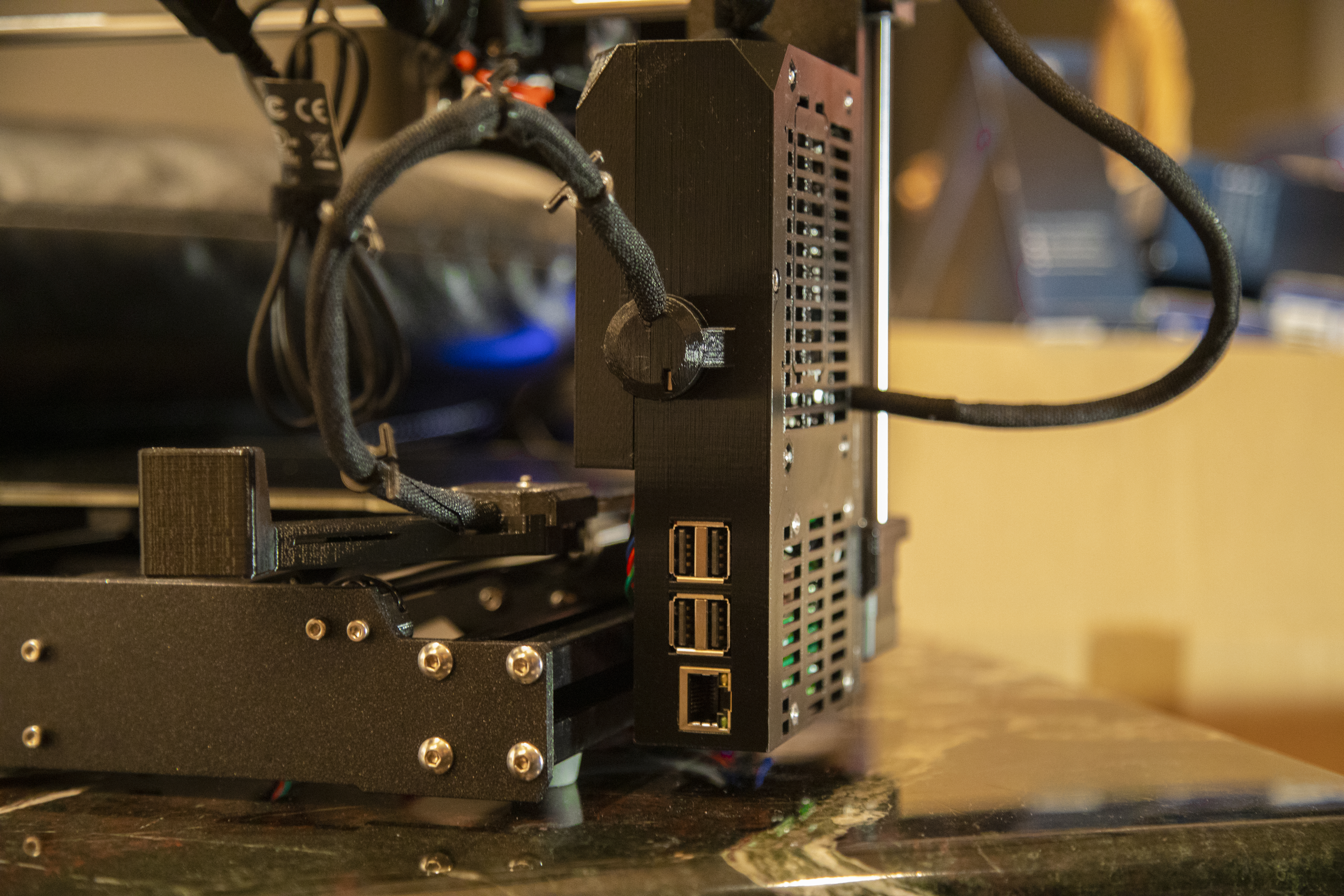
<p>This is a modification to the Original Prusa I3 MK3/MK3S Einsy case that implements appropriate housing for a Raspberry Pi 1B+/2B/3B/3B+/(4B - <strong>Now available as the first download</strong>). This part allows for one of the aforementioned Raspberry Pis to be mounted below the printer's Einsy control board.</p> <p>One might ask, "Why connect a full-sized Raspberry Pi to the Prusa I3 MK3S when it was designed to work specifically with the Raspberry Pi Zero W?" The simple response to this question would be that the Pi Zero W, while powerful enough to conduct prints, lacks the power necessary to do so concurrently with a high-resolution video stream. This is due to the Zero W's lackluster 1GHz single-core processor and 512MB of RAM. In addition to this, the developers of Octoprint, the software recommended for 3D printer control, discourage the use of their software on the Raspberry Pi Zero (W) due to this known performance deficiency, rather recommending the use of a Pi 3B or greater. With this knowledge established, one desiring to both remotely control and watch the progress of their Prusa I3 MK3(S) may deem a Raspberry Pi 3B+/4B crucial to achieving their goal.</p> <p><strong>Features:</strong></p> <ul> <li>Singular, seamless "OEM quality" case which carries Prusa's design language</li> <li>Case holds both the Einsy RAMBo and a Raspberry Pi 3 or 4</li> <li>Serial connection between Einsy and Raspberry Pi is contained within the case through the use of the Einsy's GPIO headers (Traditionally a USB A to B cable is used to connect the two boards together, however, this solution arguably "tidies up" the aforementioned unsightly wiring, preventing the use of such a large cable in order to achieve a "clean" exterior aesthetic)</li> <li>All ports on the Raspberry Pi remain accessible*<p>*Ethernet and 4 USB A ports are easily accessible from the back of the printer, while the USB power input, HDMI display output(s), and 4-pole audio/composite video output jack are accessible only when the printer is either raised, tilted on its side, or is exposed while hanging off the side of a table.</p></li> </ul> <h3>Print instructions</h3><h4>Category: 3D Printer Parts Print Settings</h4><p><strong>Printer Brand:</strong> Prusa</p> <p><strong>Printer:</strong> I3 MK3S MMU2S</p> <p><strong>Rafts:</strong> No</p> <p><strong>Supports:</strong> No</p> <p><strong>Infill:</strong> 40%</p> <p><strong>Filament:</strong> Prusament PETG Black</p> <h4>Notes:</h4><p><em>In order to achieve an identical look to the stock part, I recommend that you use the same material, Jet Black Prusament PETG which can be purchased from <a href="https://shop.prusa3d.com/en/prusament/802-prusament-petg-jet-black-1kg.html">The Prusa Shop</a></em></p> <p><strong><em>After testing I, and many others have found that while for some shorter prints it is entirely possible to power a Raspberry Pi 3B+ from the Einsy RAMBo's serial port, it typically requires additional power in excess of what the port can provide. The 5 volt regulator connected to the Einsy RAMBo's serial port is rated to a MAXIMUM output of 5 volts at 2 amps. While this amount of current is more than adequate to power a Raspberry Pi Zero W, which is rated to draw a max of approximately 1.2 Amps, both the Raspberry Pi 3 and 4 can at times draw current in excess of the available 2 Amps</em></strong> <em>(2.5A or 3A respectively),</em> <strong><em>causing them to freeze, and the print to fail as a result. Therefore, to prevent failed prints due to power loss, it would be wise to NOT connect your Raspberry Pi to the Eincy RAMBo's internal 5 volt header pin, but rather to power your Raspberry Pi with the use of an external power supply. However, should this solution be unsatisfactory, you may look at connecting your Raspberry Pi 3/4 directly to the printer's integrated power supply. I have provided links to recommended right-angle USB adapters (as there is little clearance between the Raspberry Pi's USB power port and the table) and power supplies below in the "What You Need" section.</em></strong></p> <h3><u>Post-Printing</u></h3><p><strong>Finishing</strong></p> <p>After the print is complete, make sure to clean out any stray filament around overhangs.</p> <ul> <li>Clean filament strands (or supports) from the nut recesses on the bottom of the print</li> <li>Clean filament strands (or supports) from the nut holes for each wire clamp</li> <li>Clean filament strands (or supports) from the top of the Raspberry Pi port holes (specifically the ethernet jack to ensure a perfect fit).</li> </ul> <h3><u>How I Designed This</u></h3><p><strong>Design</strong></p> <p>I designed this part with the use of Fusion 360 and Microsoft's 3D Builder. To create the part I began by importing the model of the Einsy case found on <a href="https://www.prusa3d.com/prusa-i3-printable-parts/">Prusa's website</a> into Fusion 360. Next, I created and extruded two sketches to extend the platform to house the Raspberry Pi. Promptly afterward, I imported a model of a Raspberry Pi found on <a href="https://grabcad.com/library/raspberry-pi-3-b-1">GrabCAD</a> and used it to validate my measurements for the addition. This file was used to create both properly spaced mounting and rear IO holes (after test prints I found that the hole for the ethernet jack is PERFECTLY sized, requiring additional force to be applied for the first insertion, but providing a clean, gap-free look). Finally, I exported the body and combined it with the Prusa provided Einsy case in Microsoft's 3D Builder to finalize the part and prepare it for 3D printing. (This was done due to Fusion 360 repeatedly failing to properly combine the parts to allow them to be exported as an STL for printing.)</p> <h3><u>Materials Needed</u></h3><p><strong>What you need:</strong></p> <ul> <li>Printed one of the three provided files (<em>RECOMENDED</em> reinforced_holes.stl Pictured: holes.stl)</li> <li>(6x) M3x10 screws (Salvaged from old part)</li> <li>(4x) M3nS nut (Salvaged from old part)</li> <li>(4x) M3n nut (Salvaged from old part)</li> <li>(4x) M3x10 screws (Amazon: <a href="https://amzn.to/2Viu1xu">https://amzn.to/2Viu1xu</a>)</li> <li>(4x) M3 nut (Amazon: <a href="https://goo.gl/qQmLxH">https://goo.gl/qQmLxH</a>)</li> <li>6-8 x male-female jumper pins (Amazon: <a href="https://amzn.to/31OgRdL">https://amzn.to/31OgRdL</a>) or (<strong>RECOMENDED</strong>) Prusa i3 MK3(s) to Raspberry Pi connector cable (<a href="http://bit.ly/PiPrusaCable">http://bit.ly/PiPrusaCable</a>)</li> <li>Raspberry Pi 3B+ or 4B (Amazon 3B+: <a href="https://amzn.to/336YUr4">https://amzn.to/336YUr4</a> | Amazon 4B: <a href="https://amzn.to/2pH5x51">https://amzn.to/2pH5x51</a>)</li> <li>≤ 8gb Micro SD Card (Amazon: <a href="https://amzn.to/2IrhsdU">https://amzn.to/2IrhsdU</a>)</li> <li>A USB power supply (Pi 4 USB C: <a href="https://bit.ly/Pi4USBcPower">https://bit.ly/Pi4USBcPower</a>) (Pi 3 Micro USB: <a href="https://bit.ly/Pi3microUSBpower">https://bit.ly/Pi3microUSBpower</a>)</li> <li>Angled Micro USB Extension for Pi 3 and below (Amazon: <a href="https://bit.ly/MicroUSBextension">https://bit.ly/MicroUSBextension</a>)</li> <li>Angled USB C Extension for Pi 4 and above (Amazon: <a href="https://bit.ly/USBcExtension">https://bit.ly/USBcExtension</a>)<br/> *<em>OPTIONAL</em> Raspberry Pi Fan (Amazon: <a href="https://amzn.to/31Qk0dc">https://amzn.to/31Qk0dc</a>)<br/> (not necessary, however, as there is little airflow around the Pi this will likely prevent slowdowns and errors caused by thermal throttling)</li> </ul> <h3><u>Assembly</u></h3><p><strong><em>Should disassembly necessitate more detailed instructions, please refer to the Prusa assembly instructions which can be found at <a href="https://bit.ly/mk3Selecguide">https://bit.ly/mk3Selecguide</a></em></strong></p> <p><strong>Instructions:</strong></p> <p>1.) Follow steps 1, 8, and 9, from the <a href="http://bit.ly/i3OctoprintGuide">Prusa Octoprint guide</a> in order to install and configure Octoprint on your Raspberry Pi.<br/> 2.) Uninstall the electronics enclosure from the frame of the printer by loosening the 2 M3x10 mounting screws with a 2.5mm Allen Key.<br/> <img alt="Remove the top M3x10 mounting screw" height="200" src="https://help.prusa3d.com/wp-content/uploads/prusuki/prusuki-images/gjISup6xpqRrZT55-800x600.jpg" width="266"/> <img alt="Remove the bottom M3x10 mounting screw" height="200" src="https://help.prusa3d.com/wp-content/uploads/prusuki/prusuki-images/CpyebKDgt2VKJkpB-800x600.jpg" width="266"/></p> <p>3.) Remove the Einsy RAMBo control board from the stock electronics enclosure by removing the 4 M3x10 mounting screws holding it into the case.<br/> <img alt="Remove the 4 M3x10 mounting screws" height="200" src="https://help.prusa3d.com/wp-content/uploads/prusuki/prusuki-images/iX2BNSednQdxsdl3-800x600.jpg" width="266"/></p> <p>4.) Use a small tool such as a flat head screwdriver to carefully remove the nuts from the stock part.<br/> <img alt="Remove M3nS nut from heated holder" height="130" src="https://help.prusa3d.com/wp-content/uploads/prusuki/prusuki-images/XMHeSq6cXR1F1GEJ-800x600.jpg" width="180"/><img alt="Remove M3nS nut from heated holder" height="130" src="https://help.prusa3d.com/wp-content/uploads/prusuki/prusuki-images/tsTObNRIKIoI3EPk-800x600.jpg" width="180"/><img alt="Remove 2 M3nS nut from extruder cable holder" height="130" src="https://help.prusa3d.com/wp-content/uploads/prusuki/prusuki-images/BrB3EdobgVkdVYF3-800x600.jpg" width="180"/></p> <p>5.) Clean and prepare the new electronics enclosure for installation.<br/> 6.) Install the nuts from the stock enclosure into the new enclosure.<br/> 7.) Install the additional four M3 nuts into the new enclosure to allow for the mounting of the Raspberry Pi.<br/> 8.) Install the Einsy RAMBo control board into the new enclosure.<br/> 9.)<em>EITHER</em> Connect 6 male to female Dupont connectors into the Einsy RAMBo's communication port according to the <a href="https://bit.ly/i3mk3diagram">provided diagram</a> <strong>OR</strong> Install the premade cable available from <a href="http://bit.ly/PiPrusaCable">LITTLE RED TOASTER DESIGNS</a> into the Einsy RAMBo's communication port</p> <p>10.) Install the Raspberry Pi with the software prepared in step 1.) into the new enclosure with the use of four M3x10 screws<br/> 11.) <em>EITHER</em> Connect the other end of the 6 Dupont connectors into the appropriate Raspberry Pi GPIO pins according to the <a href="https://bit.ly/i3mk3diagram">provided diagram</a> <strong>OR</strong> Connect the other end of the cable available from <a href="http://bit.ly/PiPrusaCable">LITTLE RED TOASTER DESIGNS</a> into the appropriate Raspberry Pi's GPIO pins<br/> 12.) Install the completed Octoprint Raspberry Pi 3/4 control box onto the frame of the printer and reconnect all wires to the Einsy RAMBo according to <a href="https://bit.ly/mk3Selecguide"> Prusa's official assembly guide.</a> Specifically, follow steps 8-13, 22-26, 29-38, 43, and 44.</p> <h3><u>References</u></h3><p><strong>Resources</strong></p> <p>The creation of this case was inspired by lab27's "Prusa I3 MK3 OctoPrint Raspberry Pi 3+ Einsy Case" accessible at the following link:</p> <ul> <li>OctoPrint Case used for inspiration: <a href="https://www.thingiverse.com/thing:3127643">https://www.thingiverse.com/thing:3127643</a></li> </ul> <p>Additionally, for those looking to mount a Raspberry Pi camera to their printer's bed similarly to the method depicted in the first photo, I would recommend using a derivative of burghking's "Fixed Rear Camera Mount v3 (for Prusa MK3 & Pi Cam v2.1)" accessible at the following links:</p> <ul> <li><p>Original Mount for the Early I3 MK3: <a href="https://www.thingiverse.com/thing:2802597">https://www.thingiverse.com/thing:2802597</a></p> </li> <li><p>Derivative Mount for Later I3 MK3/MK3S: <a href="https://www.thingiverse.com/thing:3032150">https://www.thingiverse.com/thing:3032150</a></p> </li> </ul> <p>Alternatively, for those wanting to mount a Raspberry Pi camera to the x-axis of their printer rather than the bed, I would recommend lab27's "Prusa I3 MK3 Raspberry Pi Camera Mount" accessible at the following link:</p> <ul> <li>X-Axis Camera Mount: <a href="https://www.thingiverse.com/thing:3121052">https://www.thingiverse.com/thing:3121052</a></li> </ul> <p>To cleanly manage the longer ribbon cable required to connect the Raspberry Pi camera, I would suggest either wrapping it around the heated bed's power wires or printing lab27's "Prusa I3 MK3 Pi Camera Cable Management [clips]" to neatly attach the ribbon cable to this wire. This model is accessible at the following link:</p> <ul> <li>Raspberry Pi Camera Ribbon Cable Management Clips: <a href="https://www.thingiverse.com/thing:3102051">https://www.thingiverse.com/thing:3102051</a></li> </ul>
With this file you will be able to print Prusa i3 Octoprint Raspberry Pi case with your 3D printer. Click on the button and save the file on your computer to work, edit or customize your design. You can also find more 3D designs for printers on Prusa i3 Octoprint Raspberry Pi case.