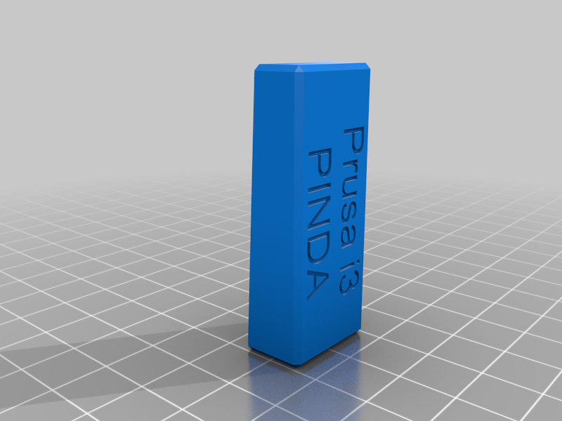
Prusa i3 PINDA adjustment tool
thingiverse
This is the tool and the process to adjust the PINDA probe position on Prusa i3 printers. The standard PINDA calibration process provided by Prusa is https://help.prusa3d.com/guide/9-preflight-check_95128 The inconvenience with Prusa process is that in Step 2 “Move the extruder carefully all the way to the right.”. It’s easy to scratch the hotbed and manually rotating the right Z motor is not convenient, too. So, here is the new process. 1. Unscrew the bolt that holds PINDA sensor and move PINDA up. Don’t pull the cable. Use a flat screwdriver to ease the PINDA holder if needed. 2. With the printer powered off move the extruder down (similar to Prusa Step 1) until it touches the hotbed. 3. Power on the printer and through Settings -> Move Axis -> Move Z, move the extruder all the way up until both sides of the x-axis assembly reach the upper point (same as during the Z calibration process). Both sides should hit the stop. X-axis assembly is horizontally leveled, now. 4. Through the same menu move the extruder down until the nozzle is around 11 mm above the hotbed. 5. Push the narrow end of the calibration tool under the nozzle. When it is stuck move the other end of the calibration tool to be under the PINDA. The text "Prusa i3/PINDA" is at the bottom of the tool. 6. Move the PINDA down until it touches the tool. See the picture. 7. Tighten the bolt holding PINDA. You are done. Congratulations!
With this file you will be able to print Prusa i3 PINDA adjustment tool with your 3D printer. Click on the button and save the file on your computer to work, edit or customize your design. You can also find more 3D designs for printers on Prusa i3 PINDA adjustment tool.