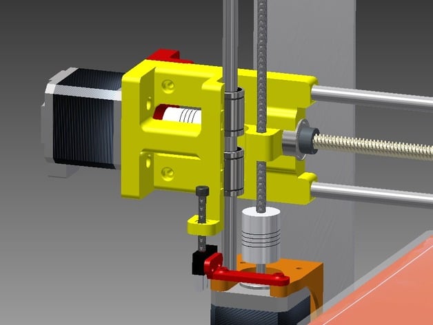
Prusa i3 X-axis lead screw upgrade
thingiverse
After dealing with inconsistencies and backlash with the belt drive design, we decided to give the lead screw a try. We started with the Y-axis for the trial, and moved onto this X-axis upgrade. Y-axis lead screw upgrade is available here New! v2.0 X-axis lead screw upgrade! Source files now available in Thing Files. Notes: All parts printed in ABS. x-end right side.STL has in-file supports for the Z-stop. (There is an alternative file available with no z-stop.) Top-Z-mounts and Bowden mount available for download in both 2 and 3-hole; uses standard Prusa frame hole dimensions. Mounts with the 625 bearing slots are available for threaded Z-rods that are approximately 300mm or greater in length. X-carriage designed with a slightly larger 8mm smooth rod spacing (to accommodate the lead screw follower). CREDIT: x-endstop holder.STL derived from ePoxi's Mechanical Y-EndStop holder for Prusa i3 (scad) here. Fantastic end stop to use. We recommend ePoxi's files for both X and Y axis end stops. Updates: Jan.19, 2015...deleted and re-uploaded all top z-mount STL files, renamed in easy to recognize left/right pairs due to so many variants in the downloads list. Mar. 28, 2015...added Inventor files (.ipt) to download list. Apr. 26, 2015...added tips under Instructions based on feedback. Jul. 13, 2015...posted update, v2.0 lead screw upgrade YouTube Video: Here is the printer in action For a closer look of the finished print (untouched): short imgur album Test print is the Deprime test object found here on thingiverse Running Repetier Host V1.0.6 and Slic3r V1.1.7 Natural ABS .15mm first layer .2mm for the rest 30% first layer speed 45mm/sec perimeters, 70% outer perimeters 60mm/sec infill, 40mm/sec top layer infill 80mm/sec travel 25% honeycomb infill (just to show rapid changes in direction) Higher print speeds are possible but, so far, this seems to be the best balance for quality. Check the Instructions tab for parts list and other important information regarding set-up. Instructions Parts List: Main parts sourced from http://openbuildspartstore.com/. Lead screw. 1000mm cut in half, save other half for Y-axis. Nut Plate Lock Collars 8mm I.D. x2 Coupler Fits Nema shaft and 8mm lead screw 608 bearing or source at a local place like Fastenal for around a $1 each. Zip ties If you don't already have some in the house, go buy a pack. M4 bolt, nut and spring For z-stop. (optional) M5 threaded rod Locally purchased (and cut) 1 meter long 5mm threaded rod for extending the z-height. Not necessary, but relatively inexpensive addition. M3 nuts, bolts, and washers Everything is M3, except: optional Z-endstop and X-endstop (which use M2.5 or very small zip ties) 625 bearing (optional Z-top stabilizer) or source at a local place. Printing Notes: Print both top and bottom Z mounts with the 8mm rod hole flat to the bed. If printing a set of top Z mounts with the 625 bearing feature, be sure to generate basic supports; supports should pop right out and be a quick, easy clean up. x-end right side.STL has in-file supports for the Z-stop. (There is an alternative file available with no z-stop.) For the (optional) x-endstop: there was a slight bit of clearance issue with the lead screw (flat back of the x-endstop mount was touching tangent to the lead-screw), causing some minor surface friction. We fixed this by simply carving/filing out a shallow relief where the rub-point was. 8mm smooth rod holes may be a bit tight/shallow. Easy fix for a custom fit is to bore it out with a drill bit (8mm / 5/16"). Be sure to print at higher infill % to maximize part rigidity. Breaking in lead-screw follower: Use ample lubrication when breaking in the nut plate, it seems very hard to turn at first. Turn the axis, by hand, from home to full range and back several times before attempting to move with the stepper motor. Steps/mm: X-axis steps should be approximately 400 steps/mm if you are using 1/16th microsteps; 100 steps/mm if you are using 1/4th microsteps. Through experience, the lead screws require more torque. Reducing to 1/4 microsteps gives you the same resolution as belt drive, but you get more torque from the stepper to maintain speed/acceleration, in depth proof can be found here.. Suggest lowering max travel speed and acceleration if there is stalling.
With this file you will be able to print Prusa i3 X-axis lead screw upgrade with your 3D printer. Click on the button and save the file on your computer to work, edit or customize your design. You can also find more 3D designs for printers on Prusa i3 X-axis lead screw upgrade.