Prusa i3 Y-axis lead screw upgrade
thingiverse
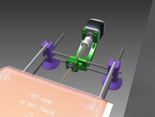
After dealing with inconsistencies and backlash with the belt drive design, we decided to give the lead screw a try. We've started with the Y-axis for the trial. So far so good!UPDATE! Our matching X-Axis lead screw upgrade is now available here!!! Along with the motor and bearing mounts, we also lifted the bead with an altered frame foot design. Please note that to keep all dimensions consistent and for this upgrade to be functional, one must utilize the new taller frame feet. Naturally, these are designed around the 8mm rod frame build. Source files now available in Thing Files. Notes: Bearing mounts must be printed with supports, easy to generate and clean up. Base printed in PLA, lead-screw components printed in ABS. CREDIT: Y-EndStop from ePoxi's Mechanical Y-EndStop holder for Prusa i3 here. Great file! Updates: Jan.12, 2015...Uploaded improved plate-follower coupler bracket.STL (added ribs for extra rigidity) Jan.12, 2015...Uploaded bed cable guide.STL as an option. Easily mounts onto the Nema 17 with zip ties. Prevents cable bundle from snagging. Jan.18, 2015...Uploaded ePoxi.i3.Y-Endstop.BetterHalfMod.STL that we are currently using. Solid end-stop design, highly recommend. Jan.21...Added YouTube video printing a test object. Mar. 28, 2015...added Inventor files (.ipt) to download list. YouTube Video: Here is the printer in action For a closer look of the finished print (untouched): short imgur album Test print is the Deprime test object found here on thingiverse Running Repetier Host V1.0.6 and Slic3r V1.1.7 Natural ABS .15mm first layer .2mm for the rest 30% first layer speed 45mm/sec perimeters, 70% outer perimeters 60mm/sec infill, 40mm/sec top layer infill 80mm/sec travel 25% honeycomb infill (just to show rapid changes in direction) Higher print speeds are possible but, so far, this seems to be the best balance for quality. Check the Instructions tab for parts list and other important information regarding set-up. Instructions Parts List: Main parts sourced from http://openbuildspartstore.com/. Lead screw. 1000mm cut in half, save other half for x-axis. Nut Plate Lock Collars 8mm I.D. x2 Coupler Fits Nema shaft and 8mm lead screw 608 bearing or source at a local place like Fastenal for around a $1 each Additional Hardware: x2 M3 x 20mm(ish) bolts x2 M3 washer x2 M4 washer (for the acme nut plate) x2 M3 x 10mm (for the y axis motor) ...all other hardware is reused from the standard prusa M8 frame Printing Notes: Bearing mounts must be printed with supports, easy to generate and clean up. Breaking in lead-screw follower: Use ample lubrication when breaking in the nut plate, it seems very hard to turn at first. Turn the axis, by hand, from home to full range and back several times before attempting to move with the stepper motor. Steps/mm: Y-axis steps should be approximately 400 steps/mm if you are using 1/16th microsteps; 100 steps/mm if you are using 1/4th microsteps. Through experience, the lead screws require more torque. Reducing to 1/4 microsteps gives you the same resolution as belt drive, but you get more torque from the stepper to maintain speed/acceleration, in depth proof can be found here. Suggest lowering max travel speed and acceleration if there is stalling. It it suggested to add some sort of "grip" on the bottom of Prusa feet. This can be accomplished by cutting out rubber circles and gluing them, or even printing off basic NinjaFlex discs. This adds a quieting effect, as well as eliminating any "dancing" that may occur on smooth workstation surfaces.
With this file you will be able to print Prusa i3 Y-axis lead screw upgrade with your 3D printer. Click on the button and save the file on your computer to work, edit or customize your design. You can also find more 3D designs for printers on Prusa i3 Y-axis lead screw upgrade.