Prusa i3 YZ Endstop Mounts
prusaprinters
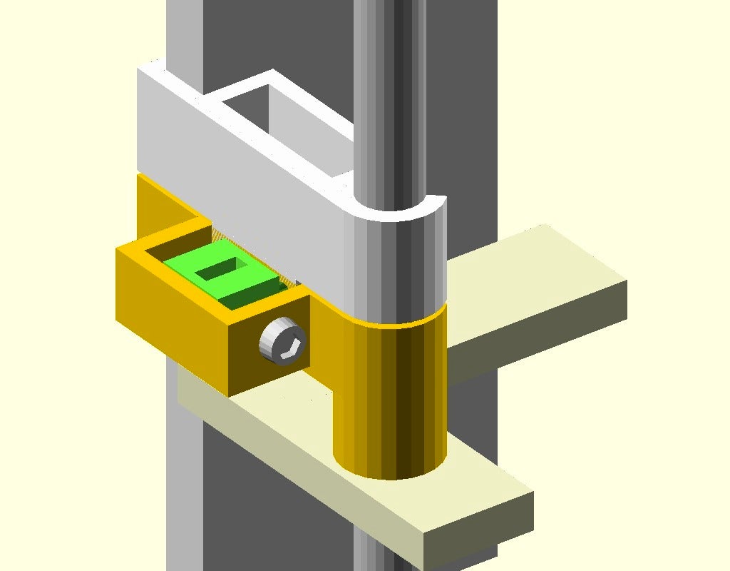
<p>Y and Z endstop mounts for the original Prusa i3. The Y endstop mount fits on the bed rods, while the front-adjustable Z endstop mount is fitted to the frame and Z rod.</p> <hr/> <p>This is my first use of a simple concept, to mount parts on the printer using clips that span two rigid points, either from the back of the frame to the front the M8 smooth rod, or between two rods. Parts built this way should be more secure, require no extra hardware, be easy to add/remove, and complement the i3 design.</p> <p>The first revision only included a Z endstop mount. It worked so well I also added a Y endstop mount that attaches to two bed rods. You may need to tune the SCAD file to get the best fit for your machine. Earlier revisions made the clips a little too short by default.</p> <p>By default these mounts are set up to hold 20mm x 10.5mm x 6mm endstops. The Z endstop is aligned lengthwise between the rod and the frame. They can be modified to accept any size endstop that will fit in the space, or even outside it with some extra hacking.</p> <p><strong>Adjustable Z Endstop Holder</strong></p> <p>Z endstop adjusters tend to be ugly and at hard-to-reach angles, so I wanted to make something easy to reach from the front. The result here uses a screw through a block that translates front-back motion into up-down motion to move the endstop holder itself on the rod and frame. By default the motion range is 2.5mm, but this can be tuned in the SCAD file.</p> <h3>Print instructions</h3><p>These mounts should work well in either PLA or ABS with any layer height. Once the SCAD parameters are tuned well for your printer the clips should be pretty tight and won't move at all. If your Z endstop is reliable you can try using the plain Z endstop holder to set-and-forget your endstop. Personally, I prefer the adjustable Z endstop holder.</p> <p><strong>Assembly</strong></p> <p>The bottom of each endstop holder is open to allow the connectors to pass through. Disconnect the endstop, run its wires through the bottom of the mount, and press-fit the endstop into the mount as far as it will go.</p> <p>It's a little tricky to get the Z home set at first. I find it helps to push in the frame end of the clip but leave the rod end loose so it will move up and down more easily. Once the Z looks good, clip the rod end to secure the endstop.</p> <p>For the adjustable Z endstop:</p> <ul> <li>Put a nut into the trap inside the slider block. </li> <li>Put the slider block into the adjuster with the square hole at the top. </li> <li>Put an M3 screw through the whole block and tighten all the way </li> <li>Put 2x M3 nuts on the end of the screw to fix it in place </li> <li>Clip the endstop holder on first, find a good height </li> <li>Clip the adjuster onto the frame, fitting the tab into the slot </li> <li>Optional: Secure the adjuster with a screw or glue </li> </ul> <p><strong>Customization</strong></p> <p>The default parameters in the SCAD and STL files are set up for my Prusa i3 built with the <a href="https://www.thingiverse.com/thing:40465">Prusa i3 Laser Cut Frame and Braces by sgraber</a>. They should be easy to rework for your particular i3, even if it's a mini. The important parameters are <code>rod_frame_gap</code>, <code>y_rods_gap</code>, and <code>frame_thickness</code>. Set the <code>rod_frame_gap</code> to the space between the M8 rod and your frame, easily measured with a caliper. Do the same with <code>y_rods_gap</code>, taking the space between the rods as a rough guideline. You can shave off ~1mm here for a tighter mount. Set <code>frame_thickness</code> to the thickness of your i3 frame.</p>
With this file you will be able to print Prusa i3 YZ Endstop Mounts with your 3D printer. Click on the button and save the file on your computer to work, edit or customize your design. You can also find more 3D designs for printers on Prusa i3 YZ Endstop Mounts.