Prusa Mini MissileToggle Switch and USB on Display
prusaprinters
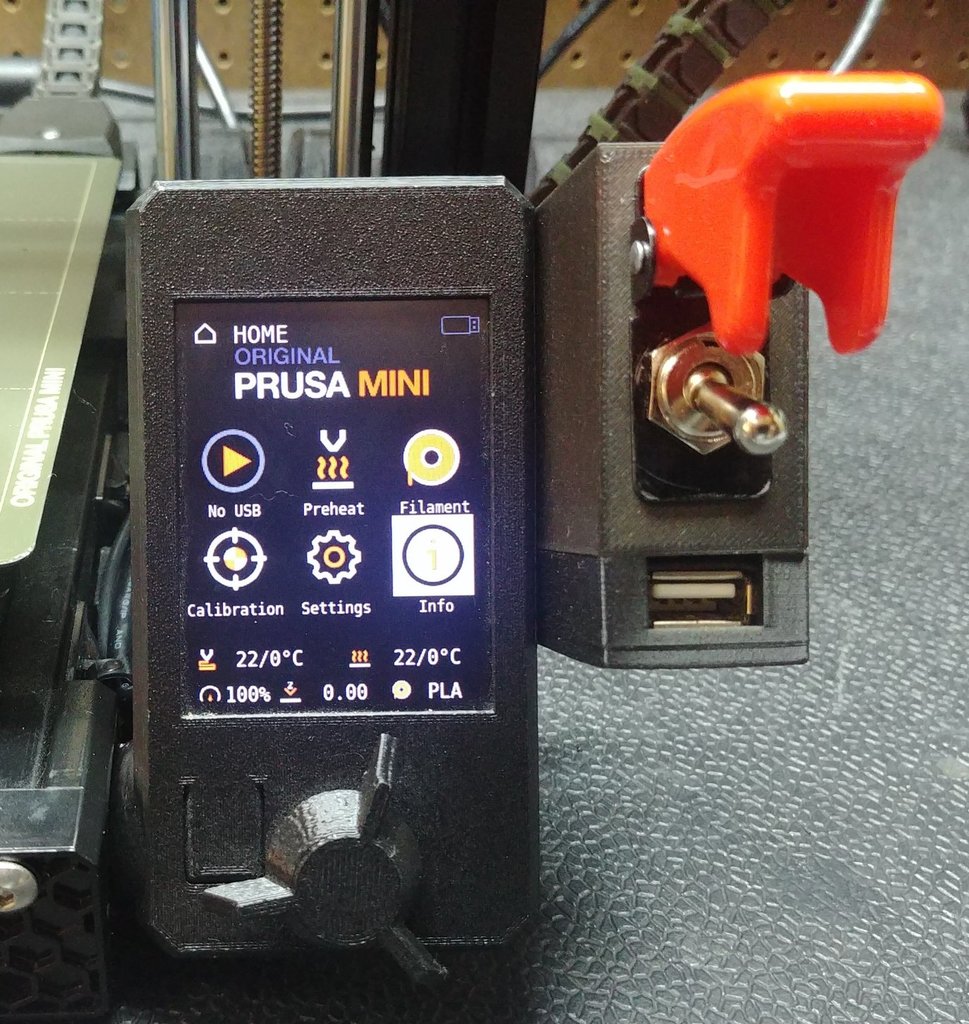
<p>Remix of 4nthonylin's Prusa Mini Display Back Cover (www.prusaprinters.org/prints/36645-prusa-mini-displaybox-cover-w-usb) to include a switchbox for a toggle switch, and an optional holder for a USB extension cable. The Mini is great within its own constraints, but the location of the power switch and USB input are a little inconvenient.</p><p>CAUTION: Install this modification at your own risk. I will provide links for what I used, but I am not an electrician and cannot guarantee the mod's safety. If you install this incorrectly, or even if you do install it correctly but I pointed you to the wrong materials, there is a risk of shorting out your board and/or causing a fire.</p><p>This is a pretty straightforward modification, but it does require cutting or melting a slot or hole in the side of the motherboard's containment box to provide an exit for the added power wires. Alternately, removing the original switch leaves a rectangular opening through which you can pass the wires.</p><p>Materials needed:</p><ul><li>x4 M3x12mm bolts to replace the 4 shorter OEM bolts that hold the display board in its casing</li><li>x1 Toggle switch of appropriate rating, with a 12.5mm (0.5in) threaded post. I used this one: www.amazon.com/gp/product/B000GTMUUI</li><li>x2 Female Spade connector appropriately sized for the toggle switch you buy (the linked switch uses 6.37mm (0.25in) connectors)</li><li>x2 Female Spade Connector 4.8mm (0.189in) to attach to the Mini's board</li><li>x2 lengths of 12g-19g high-temp braided copper wire (I used 14g because the local hardware store had it by the foot), about 50cm (20in) each will give plenty of slack to run them along the under-bed rail.</li><li>If using v2: x2 Bolts #6-32 x 0.5in and x2 nuts to attach the switchbox to the bracket on the display (which is the size I had on hand, but similarly sized M3 x 12mm bolts should work).</li></ul><p>For optional USB extension:</p><ul><li>x1 USB extension cable (Up bend, 50cm length) www.ebay.com/itm/233628431217</li><li>x2 Bolts #6-32 x 1in (which is what I had on hand, though a similarly sized M3 x 25mm bolts should work) and x2 nuts to attach the USB block</li></ul><p>I also used x2 adhesive cable tie mounts like these www.ebay.com/itm/142847677858 with the adhesive pad removed and attached to the side of the under-bed rail with T-Nuts for cable management</p><ul><li>x2 M5 T-Nuts www.thingiverse.com/thing:3663001 to secure the cable tie mounts</li><li>x2 M5x10mm bolts to secure the cable tie mounts</li></ul><h3> </h3><h3>Print Settings</h3><p><strong>Rafts: </strong>No</p><p><strong>Supports: </strong>Yes</p><p><strong>Resolution: </strong>200</p><p><strong>Infill: </strong>15</p><p><strong>Filament: </strong>PLA<br/><strong>Notes: </strong></p><p>For v1: Print cover with supports</p><p>For v2: Print display with bracket without supports, print either switchbox with supports.</p><p>Print optional USB block, no support needed</p><p>Remove power cord from the Prusa Mini before starting</p><p>Remove cover to access the board</p><p>Melt or cut a hole in the side of the board's box that the wires fit through. Be very careful not to damage any existing wiring!</p><p>Carefully remove the two short wires that connect the existing power switch to the board and put them with your spare printer parts.</p><p>Crimp a spade connector of each size onto either end of both lengths of wire. I also used heat-shrink tubing over the connector so that no metal is left exposed.</p><p>Install the toggle switch into the switchbox through the hole. I ground off the tab on the switch's plate so that I could orient the switch backwards from intended, so that the ON position can be covered and the cover must be opened to turn off the printer.</p><p>If using the optional USB extension block, place the end of the cable into the block and then attach it to the bottom of the switchbox using the 25mm (1in) bolts. If you use the USB cord I linked, you'll first have to trim some of the strain-relief off of the end of the cable to make room for the bolts.</p><p>When ready, re-insert the power cord. Flip the switch and cross your fingers.</p><p>If all is well, put the cover back over the motherboard.</p><p>If you need to resize the hole for a different switch: use Blender to open either "Switchbox v2 Rectangular Rocker (Resizable).blend" or Switchbox v2 Round Post (Resizable).blend", resize the switch cutout placeholder to what you need, then "apply" the boolean difference to the front panel, then delete the switch cutout placeholder. Note that if you are using a rectangular rocker switch, you may also need to make the front panel a little thinner than its current 4mm thickness (but be careful you don't make it too thin, or it will crack when you shove the switch in).</p><p>2021.08.07 UPDATE - I've created a better version of this with a separate switchbox that bolts onto a bracket. This allows the switchbox to be offset backwards. The first version was all one piece, but had to be far forward so it could print flat. I've also created a switchbox with a rectangular cutout that should work for smaller rocker switches. Included also are the Blender files if you need to resize the hole for the switch you have.</p>
With this file you will be able to print Prusa Mini MissileToggle Switch and USB on Display with your 3D printer. Click on the button and save the file on your computer to work, edit or customize your design. You can also find more 3D designs for printers on Prusa Mini MissileToggle Switch and USB on Display.