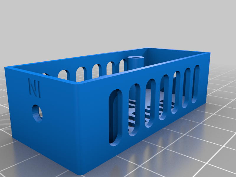
Prusa MK3S 3.5" PiTFT Mode
thingiverse
I started with this excellent design https://www.thingiverse.com/thing:3372513 and learned a few things and designed a couple of additional parts that were helpful. Additional needed hardware: * Pi 4B (2GB is enough): https://www.adafruit.com/product/4292 * PiTFT Plus 3.5": https://www.adafruit.com/product/2441 * Pi Camera V2: https://www.adafruit.com/product/3099 * Longer camera cable: https://www.adafruit.com/product/2143 * MicroSD card: https://www.adafruit.com/product/2693 * Buck converter: https://www.amazon.com/gp/product/B07N3QT628 * Red/black cable: https://www.amazon.com/gp/product/B07D74RGVM * Eye connectors: https://www.amazon.com/gp/product/B01E4RAVI0 * 90-degree USB C cable: https://www.amazon.com/gp/product/B07VJNQT6F Helpful documentation/examples I found: * Follow Octoprint installation: https://octoprint.org/download/ * PiTFT instructions: https://learn.adafruit.com/adafruit-pitft-3-dot-5-touch-screen-for-raspberry-pi/easy-install-2 * Not a Prusa but a nice example of wiring up a buck converter https://www.youtube.com/watch?v=OK7URi5LZhQ Lessons / Assembly details: 1. From the original design... the "clearance of 25mm" is CRUCIAL otherwise the screen mounts don't fit and the printer bed runs into the screen... I overlooked that multiple times. That is why I've included the "tpu_foot". They just pop into the frame. 2. In order for the PiTFT to fit into the case you have to snap the tables with circular mounts off of the unit. I used some needle-nose pliers and just bent them towards the back of the board and they snapped off easily. 3. When connecting to the EINSY board on the Prusa only the left 4 terminals come from the PSA. I originally connected to the heat-bed terminals and obviously got no power. Use a volt meter to find which terminals have power and be sure to connect to the correct red/black cables. 4. When cutting up your USB-C cable you *may* not have a black cable. Apparently this is a cost saving technique. There are typically some bare wires inside of the shield that are the black/negative wires. Printing/assembly details: 1. Use TPU to print the "tpu" parts. I used 92A SainSmart (it's really nice and squishy): https://www.amazon.com/gp/product/B08L3NDG3H 2. Other parts I printed with PLA 0.2mm. 3. The buck converter above doesn't fit in the original case (yours might) which is why I've included the "tpu_buck_converter_holder". I didn't put holes in it because I wasn't sure how it would work with TPU/infill... I printed with 50% infill on this part and then just drilled holes. Because it's TPU they "close up" so you need a bigger bit than you think. Once you've drilled the holes push the buck converter holder into the frame on the bottom. Then use a M3x5mm hex-head screw and just work it through the buck converter corner holes and into the holes you drilled. 4. These wire strippers were awesome for stripping the wire, crimping the eye connector on, etc. https://www.amazon.com/gp/product/B000OQ21CA 5. I used this camera mount: https://www.thingiverse.com/thing:4514535
With this file you will be able to print Prusa MK3S 3.5" PiTFT Mode with your 3D printer. Click on the button and save the file on your computer to work, edit or customize your design. You can also find more 3D designs for printers on Prusa MK3S 3.5" PiTFT Mode.
