Prusa Mk3S MMU2S Tower Print Buffer
prusaprinters
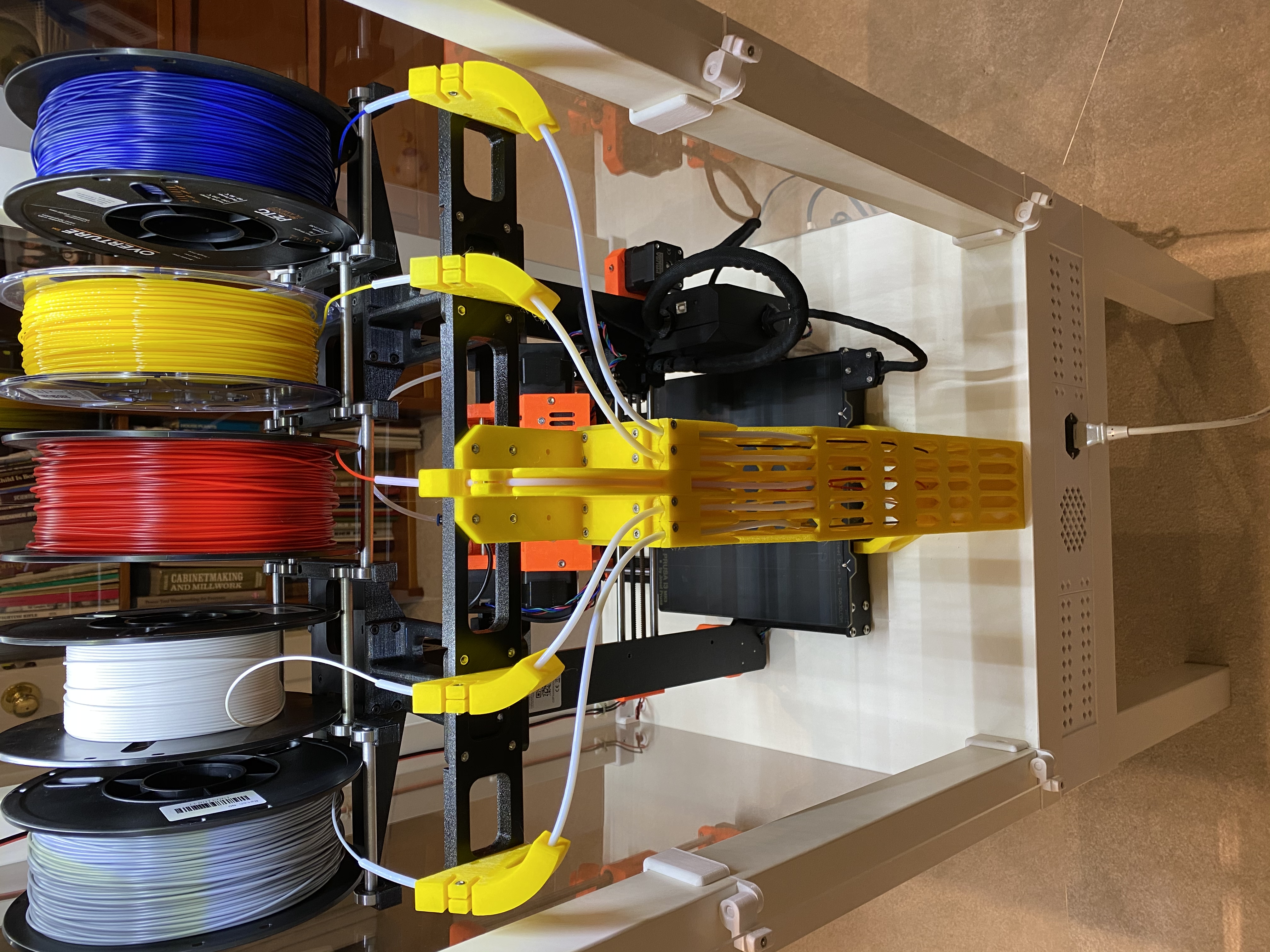
<p>This is a redesign of the MMU2S Print buffer system to relocate the 5 spools above the printer and a rear mounted vertical buffer system. It saves a lot of space, fitting within a 56cm X 56cm (22" X 22") footprint. It just fits inside an IKEA Lack enclosure that is double stacked (except the Mk3S control panel sticks out a little).</p> <p>It is also far easier to feed new filament. The MMU2S feed tubes are shortened to under 10CM and there is more space for fingers to feed filament to the MMU2S rollers. The feed from the spools is also relatively easy with a large space for hands to get in and work.</p> <p>This solution has been tested with PLA, ABS, and PETG. TPU also works but has not been thoroughly tested. Any material that can be curled into a 9cm (3.5") diameter circle should work.</p> <h3>Print instructions</h3><p>Prusa Mk3S MMU2S Tower Buffer Assembly Instructions</p> <p>Non printed parts list:<br/> M3 Square Nut 5.2 X 5.2 Square x 1.75mm Thick 44<br/> M3 Hex Nut Standard M3 Hex Nut 29<br/> M3 X 12 SHCS Standard M3 Socket Head Cap Screw 69</p> <p>Prusa MMU2S Re-used parts:<br/> 8x22 Ball Bearing (Skateboard Bearing) 20<br/> Spool Roller Tube 8MM OD Aluminum Tube (shorten) 10<br/> Filament Guide Tubing 2mm ID X 4mm OD Teflon Tube 3m</p> <p>1) Download the print files (Ready to print MMU2S single color G code and STL files for altering print setup are provided). Note: The G code files are set up to print with PETG material.</p> <p>2) Procure the commercial hardware from the parts list, M3 screws, square nuts, hex nuts, and 4mm OD x 2mm ID Teflon tubing (or re-use the existing buffer tubing).</p> <p>3) Cut the existing 10 aluminum buffer roller tubes to 10.5cm (4.25”) long.</p> <p>4) Extract and open the parts lists, 3D print parts, and commercial hardware.</p> <p>5) Print all the components. Note, a few are quite large and will take more than a day to print!</p> <p>6) Cut the Teflon tubing to length for the spool feeder section. Cut them a couple of cm longer than the lengths listed below and trim them to appropriate lengths during assembly.<br/> a. One Center tube (Spool 3): 36cm (14”)<br/> b. Two inside tubes (Spools 2 & 4): 41cm (16”)<br/> c. Two outside tubes (Spools 1 & 5): 46cm (18”)<br/> d. Five MMU2S Feeder Tubes: 9cm (3-1/2”)</p> <p>7) Remove the old print buffer assembly and tubes. Keep the spool roller bars and bearings.</p> <p>8) Install the five short MMU2S Feeder tubes into the MMU2S input side.</p> <p>9) Assembly:<br/> a. Install 4 square nuts into the main spool support legs then<br/> snap them in place. Note that the raised features are<br/> oriented to the center of the printer (toward the MMU2S<br/> Unit).<br/> b. Install 6 square nuts and 6 hex nuts in each spool support<br/> block. Note that 2 square nut slots are not used on each<br/> block, and that the nuts are installed to make a mirrored<br/> assembly. Do not install square nuts on the front-outside<br/> screw holes (they are not used). Use 4 screws to fasten each<br/> spool support block to the legs.<br/> c. Using 4 screws, attach the front spacer bar to the spool<br/> support blocks.<br/> d. Using 12 screws, attach the six spool roller guides to the<br/> spool support blocks. Note that there are left and right pairs.<br/> Insert the aluminum roller tubes in the bearings and snap a<br/> pair into each roller guide set.<br/> e. Using 8 screws, attach the two filament guide spacer blocks<br/> to the spool support blocks (on the backside of the printer).<br/> f. Install 4 hex nuts in each filament guide support block, then<br/> install the support blocks onto the filament guide spacer<br/> blocks with 8 screws.<br/> g. Install 5 hex nuts into the middle filament guide block.<br/> Loosely install the filament guide tube clamp screw. Install 3<br/> square nuts into each of the 4 bottom filament guide blocks.<br/> Loosely install one filament clamp screw into each of the<br/> bottom guide blocks. Attach the bottom filament guide<br/> blocks to the middle filament guide block.<br/> h. Snap the top half of the buffer tower to the bottom half and<br/> install it under the rear cross bar of the printer base. Snap<br/> the middle guide block into the top of the buffer tower.<br/> i. Attach the middle guide block assembly onto the filament<br/> guide support blocks using 4 screws.<br/> j. Install 2 square nuts and 1 hex nut into each of the curved<br/> filament guide blocks. Loosely install a filament guide clamp<br/> screw into each block. Install the smaller of the 4 blocks on<br/> the spool 2 & 4 area of the filament guide block using 2<br/> screws each. Install the larger of the curved blocks on the<br/> spool 1 & 5 (outside) locations using 2 screws each.<br/> k. Install the 36cm (14”) long Teflon tube into the middle (spool<br/> 3) guide block. Ensure it extends all the way down to the top<br/> edge of the tower opening and rests just inside. Tighten the<br/> clamp screw such that the tube cannot be easily pulled out<br/> and a piece of filament still slides easily through it. Repeat<br/> the installation of tubes with the next longest pieces in spool<br/> locations 2 & 4, then the longest 2 sections in spools 1 & 5.<br/> Ensure all the tubes sit about 1CM (1/2”) below the top edge<br/> of the tower lip. Use your finger to push the tubes forward.<br/> They must be able to clear the front edge of the tower and<br/> protrude out toward the MMU2S unit. Once satisfactorily<br/> installed, trim the portion of the tubes that point toward the<br/> filament spools about 5cm (2”) away from the filament guide<br/> blocks.<br/> l. Trim the MMU2S tubes to be about 3cm (1.25”) from the<br/> surface of the buffer tower. These can be adjusted a little<br/> further away for better finger clearance if soft printing<br/> materials (TPU) will not be used. Trimming too far back can<br/> cause the filament to hang up and not slide down into the<br/> buffer reliably.<br/> m. Check and tighten all the screws, center the MMU2S unit<br/> input on the buffer slots, and the assembly is ready to go!</p> <p>Setup tips:</p> <p>1) When loading spools, ensure the filament feeds from the bottom of the spool (closest to the top of the printer). Feeding from the top of the spool can cause the spool to be pulled off the rack.</p> <p>2) The shortened MMU2S feed tubes appear to work best at about 25mm (1") from the buffer. Increasing the gap improves the ease of loading the tubes from the buffer side so some experimentation may be needed to optimize this.</p> <p>3) Use the Mk3S filament load function. Feeding filament into the stock tube receptacles can be a be a problem when the filament cannot push beyond the end of the tube. Cut the filament at a diagonal and try different diagonal cut positions until you find the best angle for trouble free feeding.</p>
With this file you will be able to print Prusa Mk3S MMU2S Tower Print Buffer with your 3D printer. Click on the button and save the file on your computer to work, edit or customize your design. You can also find more 3D designs for printers on Prusa Mk3S MMU2S Tower Print Buffer.