Prusa Multi-Color Unit | RGB Individually Addressable LED Light Bar
prusaprinters
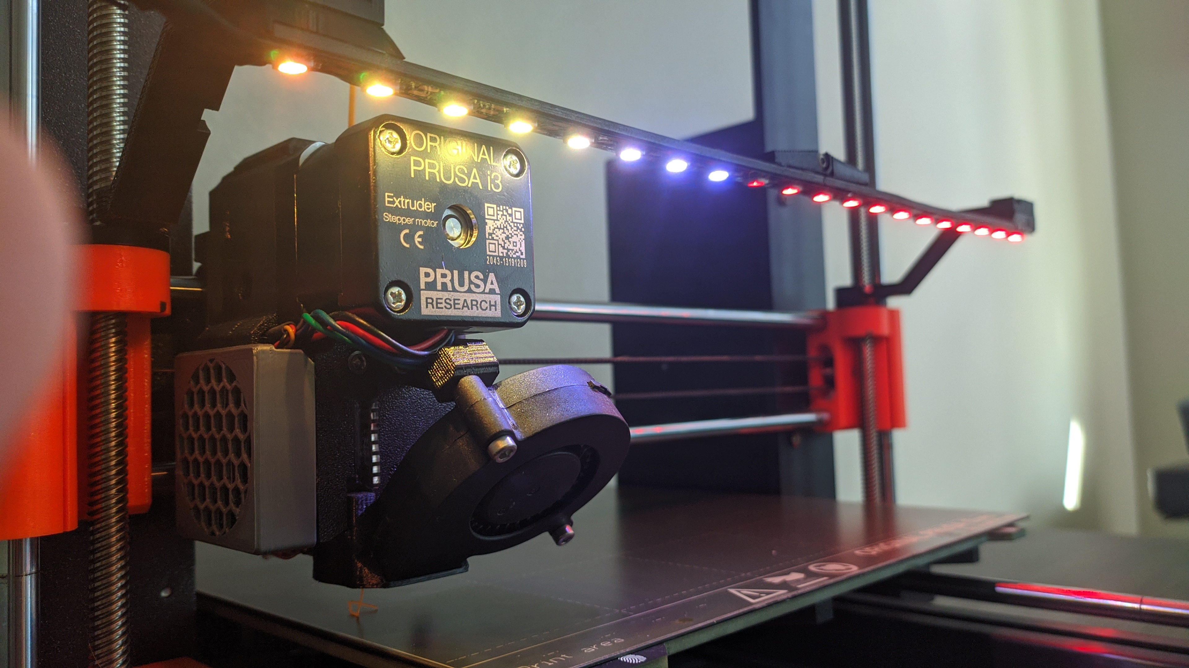
<p>This Individually addressable LED Strip moves up and down along with the X-Gantry, giving it the ability to light what's most important, your print. A button attached to the Microcontroller allows for easy toggling between Off / Reactive Mode / Full White. Controlled by an Arduino Nano, the animations change with the printer during Idling, Heating, Auto-Bed Leveling, or an Active Print with no firmware modifications. </p><p>All with one 3-pin plug.</p><p>Video: </p><figure class="media"><oembed url="https://www.youtube.com/watch?v=KOV3yoo7QTE&ab_channel=Mw"></oembed></figure><p> </p><p>Pre-assembled kits here: <a href="http://etsy.me/3cjWayl">http://etsy.me/3cjWayl</a></p><p> </p><p>Additional Information:<br/>- Only compatible with the PRUSA MK3/MK3S/MK3S+<br/>-This will not work if you are POWERING a Raspberry PI Zero off of the Printer's Einsy Rambo. The PI Uses the same pins as the PRUSA MCU and thus will not work<br/>-Uses 5V WS2812 Individually Addressable LEDs<br/>-Compiled with the Arduino FastLED libray<br/>-Max current draw ~300 mA<br/> </p><p><strong>Mandatory Parts list: </strong></p><p><a href="https://www.amazon.com/LAFVIN-Board-ATmega328P-Micro-Controller-Arduino/dp/B07G99NNXL/ref=sr_1_2_sspa?dchild=1&keywords=arduino+nano&qid=1616458143&sr=8-2-spons&psc=1&spLa=ZW5jcnlwdGVkUXVhbGlmaWVyPUFXVk1MSUU3MVkwM0smZW5jcnlwdGVkSWQ9QTA0NzQ3NTgxWTJDUllBWlFERlQyJmVuY3J5cHRlZEFkSWQ9QTA3NDEzMDBGMFZQRkZKTEcxU1cmd2lkZ2V0TmFtZT1zcF9hdGYmYWN0aW9uPWNsaWNrUmVkaXJlY3QmZG9Ob3RMb2dDbGljaz10cnVl">Arduino Nano</a> </p><p><a href="https://www.amazon.com/ALITOVE-Individually-Addressable-Programmable-Compatible/dp/B086B8Z6BK/ref=sr_1_8?dchild=1&keywords=individually+addressable+led+strip&qid=1616458170&sr=8-8">Individually Addressable LED Strip</a></p><p><a href="https://www.amazon.com/gp/product/B0899Y1RSX/ref=ppx_od_dt_b_asin_title_s00?ie=UTF8&psc=1">Bamboo Sticks</a> or Popsicle Sticks</p><p><a href="https://www.amazon.com/gp/product/B0774NMT1S/ref=ppx_yo_dt_b_asin_title_o00_s00?ie=UTF8&psc=1">Dupont connectors</a></p><p>M3x20 x2 & M3x8 x1 (Should be some left over in the PRUSA kit)</p><p><a href="https://www.amazon.com/gp/product/B00R17XUFC/ref=ppx_od_dt_b_asin_title_s00?ie=UTF8&psc=1">Tactile Button</a></p><p><a href="https://www.amazon.com/ANBES-Soldering-Iron-Kit-Electronics/dp/B06XZ31W3M/ref=sr_1_5?dchild=1&keywords=soldering+iron&qid=1616458354&s=industrial&sr=1-5">Soldering supplies</a></p><p><a href="https://www.amazon.com/gp/product/B08JPLRXRK/ref=ppx_od_dt_b_asin_title_s00?ie=UTF8&psc=1">3 Strand Wire</a></p><p>Small Zipties</p><p>Wire Strippers / Crimpers</p><p>Hot Glue</p><p>Double Stick Tape </p><p> </p><p><strong>Optional:</strong></p><p><a href="https://www.amazon.com/gp/product/B085RC16VK/ref=ppx_od_dt_b_asin_title_s00?ie=UTF8&psc=1">JST-SM Connectors</a></p><p><a href="https://www.amazon.com/gp/product/B07WWWPR2X/ref=ppx_yo_dt_b_asin_title_o00_s00?ie=UTF8&psc=1">Heat shrink</a></p><p><a href="https://www.amazon.com/gp/product/B071JH14WZ/ref=ppx_yo_dt_b_asin_title_o00_s00?ie=UTF8&psc=1">Braided Wire Sleeving</a></p><p><a href="https://www.amazon.com/gp/product/B07LFWTPZ8/ref=ppx_yo_dt_b_asin_title_o01_s01?ie=UTF8&psc=1">Black spray Paint</a> (Could use a sharpie as well)</p><p> </p><p>If you buy the pre-assembled kit, you can skip all the steps below. Thanks for supporting me.</p><p><strong>Step 1 - LED Light Bar Assembly</strong></p><ul><li>Paint/Color a 13" long wooden stick for the LEDs. It makes it look much better. Attach the LEDs to the wood after paint has set.</li><li>Solder onto the LEDs about 7" of wire. Apply the heat shrink and the braided sleeving.</li><li>On the end, attach male JST-SM connectors or male Dupont connectors.</li></ul><figure class="image image_resized" style="width:80.89%;"><img src="https://media.prusaprinters.org/media/prints/60857/rich_content/5cca09dc-ef61-455e-88ec-d579a28394da/mvimg_20210323_181709.jpg#%7B%22uuid%22%3A%22e8ba5dab-f8c4-4a86-a956-014df0b84d3b%22%2C%22w%22%3A3840%2C%22h%22%3A2160%7D"/></figure><p><strong>Step 2 - Prepping the Electronics</strong></p><ul><li>Gather a 3 Strand wire about 9" long. On one end attach male Dupont connectors to all three colors. <strong>(Wire A)</strong></li><li>On the opposite end, attach one female Dupont connector to the GREEN (signal) wire.</li><li>Strip off long amounts of wire on the remaining red / white wires.</li></ul><figure class="image image_resized" style="width:80.12%;"><img src="https://media.prusaprinters.org/media/prints/60857/rich_content/e0b1bf2a-3cab-4a15-850f-e3c4e0217068/mvimg_20210323_182221.jpg#%7B%22uuid%22%3A%22f916199f-dcca-4279-bd25-537be49b03dd%22%2C%22w%22%3A3840%2C%22h%22%3A2160%7D"/></figure><p> </p><ul><li>Create another 3 Strand wire about 2" long <strong>(Wire B)</strong></li><li>On one end attach female JST-SM connectors or female Dupont connectors (this directly attaches to the LED light wires)</li><li>On the opposite end, attach one female Dupont connector to the GREEN (signal) wire.</li><li>Strip off long amounts of wire on the remaining red / white wires.</li></ul><figure class="image image_resized" style="width:75.71%;"><img src="https://media.prusaprinters.org/media/prints/60857/rich_content/2d987dba-5407-4e7a-9607-44c53d6d59a7/img_20210323_182536.jpg#%7B%22uuid%22%3A%22b00bec32-753f-42b0-93cf-132a5a67ae61%22%2C%22w%22%3A3840%2C%22h%22%3A2160%7D"/></figure><ul><li>Create <strong>TWO</strong> 2-strand wires that are approximately 2.5" in length. <strong>(Wire C & Wire D)</strong></li><li>Attach female Dupont connectors to one end and on the other end strip off long amounts of wire</li></ul><figure class="image image_resized" style="width:74.26%;"><img src="https://media.prusaprinters.org/media/prints/60857/rich_content/b2c8bec3-83d6-4f59-8f24-720c461e3f45/mvimg_20210323_182610.jpg#%7B%22uuid%22%3A%223f3dabc6-d6ee-424d-8e83-9556e230bf5d%22%2C%22w%22%3A3840%2C%22h%22%3A2160%7D"/></figure><p><strong>Step 3 - Soldering</strong></p><ul><li>Solder <strong>Wire C </strong>to <strong>OPPOSITE</strong> prongs on the tactile button.</li><li>Solder the red wires from <strong>Wire A & B</strong>. Then solder one strand of <strong>Wire D </strong>to the red wire, effectively tapping into the +5v wire.</li><li>Soldering the white wires from <strong>Wire A & B</strong>. Then solder the other strand of <strong>Wire D </strong>to the white wire, effectively tapping into the ground wire. The green wires from each end will connect to the Arduino.</li></ul><figure class="image image_resized" style="width:75.05%;"><img src="https://media.prusaprinters.org/media/prints/60857/rich_content/b9c42656-1551-4198-b4fa-8ebfde618f52/mvimg_20210323_182815.jpg#%7B%22uuid%22%3A%221cefb0ff-5254-4a93-8640-53fa1539c5e4%22%2C%22w%22%3A3840%2C%22h%22%3A2160%7D"/></figure><p><strong>Step 4 - Electronics Assembly</strong></p><ul><li>Insert the “Arduino No Mess up Connector” onto the Arduino. The notch should be on the same side as the USB port and It should sit <strong>flush</strong> with the pins. This helps when connecting all the wires.</li></ul><figure class="image image_resized" style="width:87.98%;"><img src="https://media.prusaprinters.org/media/prints/60857/rich_content/5f88202b-5295-42fc-b0d9-5c41bd56d6c7/mvimg_20210323_185049.jpg#%7B%22uuid%22%3A%227c657df2-9de5-469d-91b6-d235d8c1ae3e%22%2C%22w%22%3A3840%2C%22h%22%3A2160%7D"/></figure><p> </p><ul><li>Insert and glue the Tactile button from the side where a weird bevel is sticking out for the “Light Controller - Lid"</li><li>Follow the wiring diagram below to plug in all the connections to the Arduino. Don't do anything with the Einsy Rambo yet.</li></ul><figure class="image image_resized" style="width:100%;"><img src="https://media.prusaprinters.org/media/prints/60857/rich_content/82f51395-76af-43fa-afca-a1575fc6a935/prusa-mcu.png#%7B%22uuid%22%3A%229c2cce19-8d63-4b1e-92a7-9b8fc2f8be88%22%2C%22w%22%3A1398%2C%22h%22%3A696%7D"/></figure><ul><li>Insert the Arduino and all its' wires into the Light Controller box. The wires that go to the LED Strip should come out on the same side to where the Arduino's USB port is.</li></ul><p><strong>Step 5 - Flashing the Arduino</strong></p><ul><li><strong>WITH THE LED LIGHTS UNPLUGGED FROM THE ARDUINO & PRINTER, </strong>go <a href="https://drive.google.com/drive/folders/1Oo1-Gey8sa5l-RtscI2WKcTNIKpXrQCS">here </a>and flash the Arduino with the Sketch titled “3D printer lights"</li></ul><p><strong>Step 6 - Printer Assembly</strong> </p><ul><li>Follow the assembly guide <a href="https://drive.google.com/drive/folders/1Oo1-Gey8sa5l-RtscI2WKcTNIKpXrQCS">here</a>. Note that you will need to use cable ties in order to attach the LEDs to the printer.</li></ul><p> </p>
With this file you will be able to print Prusa Multi-Color Unit | RGB Individually Addressable LED Light Bar with your 3D printer. Click on the button and save the file on your computer to work, edit or customize your design. You can also find more 3D designs for printers on Prusa Multi-Color Unit | RGB Individually Addressable LED Light Bar.