PSMD (Pololu Stepper Motor Driver) Triple Axis Driver
thingiverse
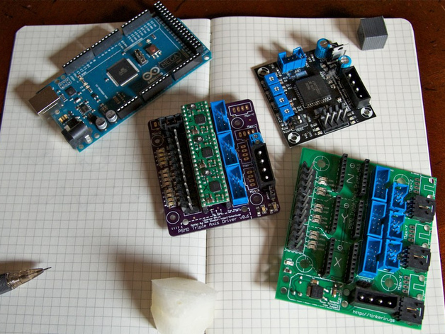
Introducing a drop-in replacement for MakerBot stepper drivers, all three axes are contained on a single board. Order from http://www.tinkerin.gs/p/psmd-pololu-stepper-motor-driver-triple or Seeed Studio! New version is smaller with dip switches for microstepping configuration. It now runs at eight times higher resolution, making it smoother and quieter. Based on MakerBot Stepper Driver v3.0, but with notable exceptions: Pololu A4983/A4988 stepper motor driver carrier board is used for each axis, removing circuitry already on the Pololu board, using CD-ROM-style connectors from Gen4 electronics, and more. The board is etchable and hand-solderable with exception of thru-hole capacitor leads. Place Pololu boards vertically for hot air flow past them; if overheating occurs, a 12V CPU fan can be added. Assembly instructions provided with updated eagle files. Kit currently out of stock; professionally made versions expected soon.
With this file you will be able to print PSMD (Pololu Stepper Motor Driver) Triple Axis Driver with your 3D printer. Click on the button and save the file on your computer to work, edit or customize your design. You can also find more 3D designs for printers on PSMD (Pololu Stepper Motor Driver) Triple Axis Driver.