Qidi Xpro upgrade to Lerdge K
prusaprinters
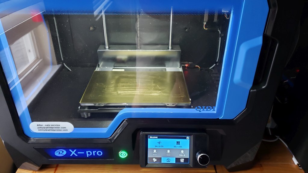
<p>After a couple years the motherboard / mainboard in my Qidi Xpro suddenly died. After checking the normal things and testing the caps, mosfets etc on the board it seemed like it might be beyond my repair skills. A replacement board from Qidi was ~$140US which didn't sit to well with me. I had an older MKS board and display kicking around but really never like Marlin that well and never got very good prints from it. Seeing a review on the Lerdge K I ordered the entire kit from their website for ~117US shipped. It arrived 2 weeks later and I began the process of converting it over. Part of this evolution was to ditch one of the extruders. The Lerdge K is dual capable but I rarely used both and often found the 2nd one more of a nuisance with leveling than anything else. I also used this opportunity to add a BL touch to the mix by using this great item <a href="https://www.thingiverse.com/thing:4604839">https://www.thingiverse.com/thing:4604839</a> I just need to make some tweaks to make it fit better with my needs. I printed this part in Black Poly Carbonate Carbon Fiber.</p><p>This write up is going to be a work in progress as I have time to add more details and share what I learned. I'll start that journey though by saying this, it was worth it. Worth it enough that I'll probably buy another kit and voluntarily convert my other printer a Qidi Xplus as well. The display adapter pictures are some of the first prints off the conversion with zero changes in settings from Cura.</p><p>The first thing I made was the mainboard adapter, ironically it will be the next thing I change. I'm going to redesign it because I made this to bolt to the factory mounts for the Qidi mainboard and line up with the side opening on that printer. My intention was to have the Lerdge connections be accessible from the side like the factory and so I enlarged the opening with my Dremel but it just doesn't work well since the factory board connections were designed to stick out further to compensate for the mounting position. I want to move the board a little more inward and I'll plug the hole and run a microSD & USB extension elsewhere to use.</p><p>The mosfet mounts are the same ones published on Lerdges site except I enlarged the holes a bit and added a 5th ear to give me mounting options.</p><p>The display is where I spent quite a bit of time and really pushed the limits of Sketchup's capabilities. The stock display is a 5" touchscreen and the Lerdge is a 3.5" touchscreen but since it has a rotary encoder (optional, you need to solder it on) the boards where almost the exact same size. I did not want to cutup the stock screen opening, it would have been easier. I also didn't want exposed screws or bolts visible from the front. So I made a 2 part kit that bolts the board in the angled display adapter and to the snap in mount. So this is 100 removeable and serviceable with out hacking up the stock opening. This way if a new display comes out I want it's just a matter of changing that from angled part.</p><p>I plan on filling more details on setting this up for anyone else interested so please have patience. For those who can't wait I also included my Lerdge configuration files.</p><p>Update #1:</p><p>When switching to a single nozzle I decided to keep the nozzle on the right hand side. This was primarily to retain the stock X-axis endstop without having to design a part to trigger it. The option to use switchless endstops with the TMC2209 drivers is there but I tried to keep the project to a manageable scope out of the gate.</p><p>In the factory hotend, the stock thermocouple is not supported in the Lerdge firmware. Being that I'm a big fan of the screw in style versus the glass thermistors I needed to order a new MK10 heating block from <a href="https://amzn.to/3D6yHxX">Amazon</a> which has both 3mm & 4mm screws for the temp sensor. I could not find any screw in thermistors that use the stock 3mm thread that would arrive in a reasonable amount of time. I did find a NTC100K in 4mm though and it's been working well. My nozzle on the right hand side ended up having a home offset of X=33.00, Y=3.50 & Z=0.00 with the BLTouch offset from the nozzle being X=-31.00, Y=-11.00 & Z=-0.40. Your not going to want to try and fine tune these on your machine though until you have stepper steps dialed in perfect. This was a bit tedious and discussed below some.</p><p>The bed was plug and play really it already uses a NTC100K thermistor so it was uneventful hooking that up. The bed is of course set to 230x150x150 and the max travel set in the firmware I found to be 264x155x153 and I set a 5mm edge. This mainly affects the BL touch as without it the auto leveling tries to go to 0,0,0 and my spring steel build plate is ever so slightly rounded and misses it or skips off the bed corner driving the head into the build plate.</p><p>The endstops as mentioned remained needed to be changed from the stock 4 wire setup to the 3 wire JST plug used on the Lerdge. I recommend you buy an assortment pack of these connectors somewhere like <a href="https://www.amazon.com?linkCode=ll2&tag=thingiverse09-20&linkId=e4759bff1fa9a55a0f897d801ce2d765&language=en_US&ref_=as_li_ss_tl">A</a><a href="https://amzn.to/3MF13Ch">mazon</a> for ~10USD before starting as many plugs need to be changed over. I've always used needle nose pliers in the past to make these or even soldered the wires to the crimps. I felt this was a good time to wire a good wire fitting crimper that could do the JST plugs for this project. Once I figured out how to set the pressure on it and stopped breaking wires it does a nice job for ~$20USD. The endstops are all configured as normally open and use a "low" trigger.</p><p>Steppers, this could be a very large section so I'll try to keep it reasonably brief. Starting with the drivers, I opted for the TMC2209's with my kit and after watching the Kersey Fabrication review on YouTube I new I needed to solder the pad on the underside of the chip first in order to enable the UART mode. You also need to verify the factory voltages on the steppers, the notes from Ledge indicate a range of like 1.2 to 1.3v on these and the firmware defaults all of them to 1.25v. This wasn't the case for me as I had one as low as 1.02 I think it was and one mid 1.3's most were in the 1.teens. You'll want to get these as close to 1.25v as possible and update the voltage in the firmware with the exact voltage. TMC2209s use the current to control the stepper load and the voltage is a reference point for that. So no dropping the volts down to reduce heat like with the older 8825's for example. I went with a 32 microstep on mine setup and I know there is 1.7 gazillion for microstepping and 1.7 gazillion against it. I wanted quieter as this little printer rarely if ever see's the kind of stepper load where it runs out of torque and starts missing steps. I can say it is remarkably quieter to print now especially with changing all the fans (except the parts cooling one but I'm working on something there) over to nice Noctua's. My steppers are all set to reverse in the firmware since the endstop triggers are at max X, Y & Z. So as you can imagine those endstops are all set to home at X, Y, & Z max.</p><p>One of the most tedious and boring parts of this process was fine tuning the steps for each stepper. See Qidi Tech doesn't publish a whole lot of info on their parts and to make things worse they use odd sizes for belt pulleys. I counted and measured and plugged them into online calculators which got me close but not close enough. So what I ended up doing first was X homing and rigged up my micrometer with a bunch of magnets and zeroed it out on the extruder stepper. Then I sent a move 100mm command on the X-axis and measure and make adjustments to the steps. If you ever do something like this, change the movement speed of the motors way down. If they are set fast it moves the micrometer so fast it became inaccurate and less repeatable. I had it moving quite slow (think it was like 10mm/s) and would repeat the test 3 times and assuming they were very close make an adjustment to the steps. The remeasure and repeat multiple time till it would give me repeatable movements within 5 hundredths of a mm i.e. 0.05mm. I could not attain more repeatable accuracy with my $20 digital micrometer. This was repeated with the other other 2 axis until I felt it was as close as I thought I could get it. Now that I felt comfortable with the steps which ended up being X=187.86, Y=189.50, Z=804.0 and E0=96.0 (this was done the traditional way of measuring and marking 100mm of filament). Now was the time to figure out the offsets for the nozzles. I did this by inserting a nozzle cleaning rod (little acupuncture looking needle) out the bottom and microstepped the head exactly over the right end and front of the bed. This was 33 & 3.5 as mentioned above. Now I could home the printer and send it to 0,0,0 and the needle should go right to the front left corner which it did.</p><h3>Print Settings</h3><p><strong>Printer:</strong></p><p>Qidi X-Pro</p><p><strong>Rafts:</strong></p><p>No</p><p><strong>Supports:</strong></p><p>No</p><p><strong>Resolution:</strong></p><p>.15</p><p><strong>Infill:</strong></p><p>20</p><p><strong>Filament:</strong> Hatchbox PLA</p><p>Black</p><p>Category: 3D Printer Parts</p>
With this file you will be able to print Qidi Xpro upgrade to Lerdge K with your 3D printer. Click on the button and save the file on your computer to work, edit or customize your design. You can also find more 3D designs for printers on Qidi Xpro upgrade to Lerdge K.