Quadrifilar Helix Antenna Cross Arms Drill Guide
thingiverse
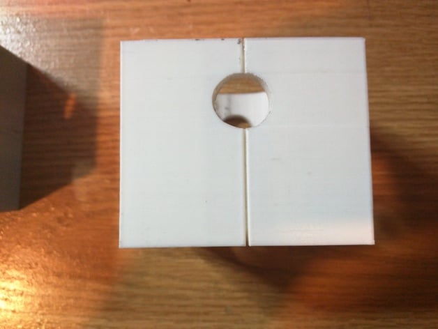
These drill guides were designed in order to create a Quadrifilar Helix Antenna (QFH) using an infinite balun design tuned to 137.5 MHz for the NOAA 19 Satellite as described below: Original Build Guide:http://www.qsl.net/yo4tnv/docs/ARRL%20UHF%20Microwave%20Projects%201997.pdf (Page 1-39) Step by Step instructions:http://www.rish.kyoto-u.ac.jp/digitalbeacon/information/Building_QFH_Antenna_Guide.pdf Dimensions of Pipes Used: Center Column: 2 inch PVC pipe with an outer diameter of 2.4 inches Leg pipes: 1/2 inch PVC pip with an outter diameter of 0.6 inches Words of Caution: This antenna drill guide is only for constructing a QFH antenna tuned to 137.5 MHz. You could potentially get away with anything around the 137 MHz region but it is definitely not suited for wifi or short wave radio. So that being said don't print and hope that your antenna will work using these drill guides. Design & Test Adventure: Since I did not have a drill press that was capable of drill through holes I tried many techniques to drill the arm holes at 90 degree angles with no luck. I would either end up with weird offset holes that were out of angle or I would get holes that looked perfect and when I fit the cross arms in the arm holes would look way out of angle. So to fix the problem I looked into 3D Printing some drill guides. After research and some time designing (and redesigning) these guides using tinkerkad I finally settled on this model. Had them printed and used the slotted line to line up with the drill targets I made for easier alignment (added perpendicular lines to step 5 and 6 from the step by step guide for each of the leg holes markings) then marked the holes and presto perfectly aligned 90 degree holes. You can see the final results in the actual antenna that is now mounted outside. The cross arms holes in the main column are what these drill guides are for. Because of my success with this first every 3D Print I have proudly bought a FlashForge Creator Pro 2016 model which has proven the best investment I made since my university education. Future Changes: In the future I would like to modify this design to reduce the leg holes to a simple point which you could mark with a tip of a pencil. I believe the current design was a bit clumsy (although it works well) since some users may use different size piping than the one recommended in the step by step guide mentioned above. Another addition would be to add horizontal groves in order to align with the markings that are drawn around the perimeter of the center main column. If time permits I will upload the aforementioned fixes. Print Settings Printer Brand: MakerBot Printer: MakerBot Replicator 2X Rafts: No Supports: Yes Resolution: 0.3 Infill: 15% Notes: This was printed on a makerbot over at Makerthings in Montreal Canada. The print settings I have above seem to be correct and what I remember the clerk telling me he used. In the end this design is easy to print so you can use whichever settings you feel comfortable with. Post-Printing Post Printing After you print these drill guides I noticed that not all 2 inch and 1/2 inch pipes are the same so you may have to sand the holes so like that your pipe fits. Other than sanding holes there is nothing else that needs to be done.
With this file you will be able to print Quadrifilar Helix Antenna Cross Arms Drill Guide with your 3D printer. Click on the button and save the file on your computer to work, edit or customize your design. You can also find more 3D designs for printers on Quadrifilar Helix Antenna Cross Arms Drill Guide.