Raise3d gcode terminal switcher
thingiverse
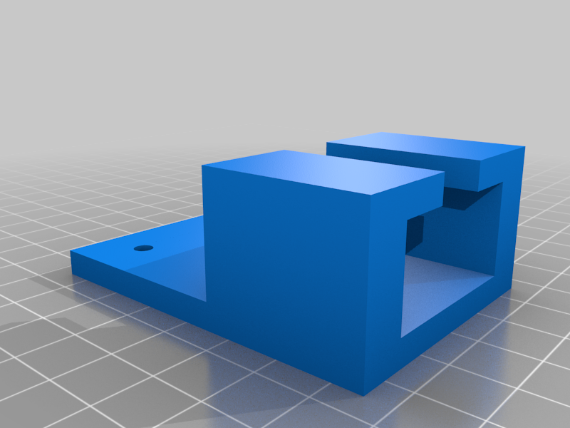
Adds pronterface interface to the Raise3d n2 series. USB switcher box allows for switching between LCD control and terminal control. Previously the only way to give custom gcode to the n2 plus was to either open up and unplug the main board or update the starting gcode. Demo: https://www.youtube.com/watch?v=Vl5a_q15wbE Amazon link to switching box https://www.amazon.com/EEEKit-Printer-Scanner-Sharing-Splitter/dp/B009OU8PRC/ref=sr_1_13?dchild=1&keywords=2+ports+usb+type+b&qid=1632411380&sr=8-13 Background: The way the N2 series of printers is configured is similar to a standard printer running something like klipper or octoprint. When a print is started the mainboard does not get access to the entire gcode, the processor in the LCD does. Think of the LCD as the raspberry pi with a screen attached. The LCD communicates gcode to the mainboard over a usb 2.0 type B printer cable. The male type A side plugging into the lcd and the male type B plugging into the mainboard. This mod takes that cable and instead of it's final destination being the mainboard, it is a swithcing box where the button that is pressed determines which input signal makes it to the mainboard. One cable goes from the LCD to the box, another goes from the laptop to the box, and the final goes from the box to the mainboard (said in type A to type B order). Installation: Optimal placement for the box is just above the mainboard enclosure and strong double sided tape will be more than enough to hold it to the frame. The included cable will not be long enough to reach up here so something longer is needed. (recomended 5 foot cable included with the box) The cables for the LCD are plugged in under the housing and require loosening of the cable track before removal. If your fingers are skinny enough full removal is unnecessary. The cable is a standard translucent blue USB type A male on this end. Lay the printer on its back and attempt to remove the bottom cover. (in my installation the bottom cover was impossible to unscrew without stripping) The type A cable will be tied in with 2 zip ties. Tip the printer back on it's wheels. Open the mainboard box in the back right of the machine. The blue cable unrouted previously will be plugged into the bottom of the mainboard and held in place by a zip tie. Remove this zip tie and pull the cable out from the bottom. The cable should be free at this step. This cable can be reused for connection to the laptop. Take the longer cable and plug the type A end into the LCD. Flip the printer back on it's back and run the longer cable back the way the other one was. Tie points are optional. Instead of running it up the mainboard hole, run the cable up the track just behind the mainbord housing the stepper motor cables. Flip the printer back on its wheels. There should be enough room between the bottom of the track and the frame to squeeze the cable out and run it up to the switcher box. Plug Type B connector into USB 1. Run a smaller cable (recommended 2 feet) from the switcher box to the mainboard. At this point you can press the button corresponding to the LCD input cable and power on the printer. If all went according to plan nothing should be different. The final step is to take the file listed above and bolt it on to the 2 m4 bolts holding on the corner nearest the hinge on the back pannel. Replace these bolts with m4x12 and attach the printed holder. This is meant to keep the printer mobile and reduce cabble dangle. For bonus points you can use a male to female cable like https://www.amazon.com/Printer-Extension-Adapter-Connections-Scanner/dp/B071P2BGK5/ref=sr_1_20?crid=3RLQM73FU499U&dchild=1&keywords=usb+type+b+male+to+female&qid=1632419395&sprefix=usb+type+b+male+to+f%2Caps%2C165&sr=8-20 and drill a hole in the outside of the printer for mounting. This looks a little cleaner and is a little easier if you want to have flexibility with how far you can communicate with the printer in the future. Run a cable from USB 2 down the same channel and bring it outside the printer. Bundle it up and stick it in the holder. Hardware is done. The final final step is to change the bualdrate in whatever communication software you use to what the lcd outputs. On my n2+ this number is 230400
With this file you will be able to print Raise3d gcode terminal switcher with your 3D printer. Click on the button and save the file on your computer to work, edit or customize your design. You can also find more 3D designs for printers on Raise3d gcode terminal switcher.