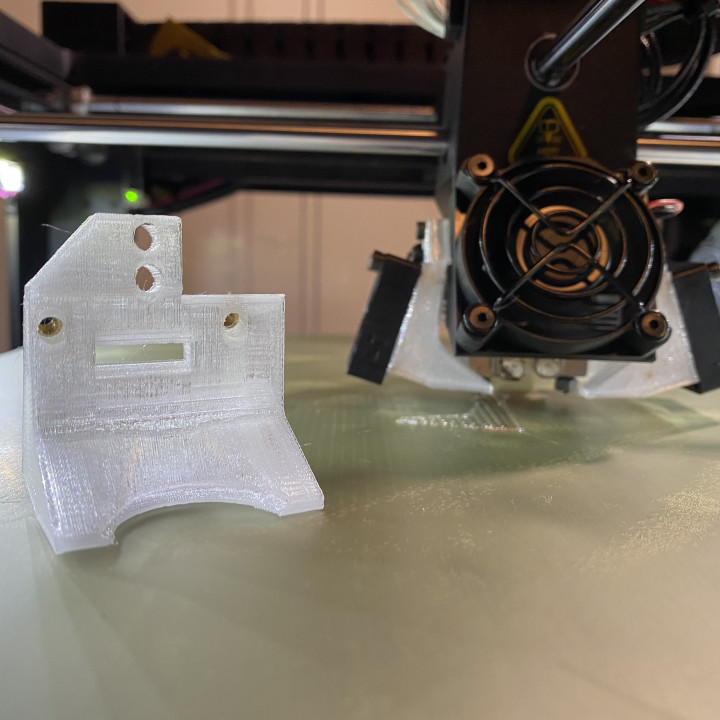
Raise3d Pro2 Fan Shroud for Copperhead Hotend
myminifactory
This fan shroud is a remix of a previously unpublished design by James Weishaar who is active in the Raise3d groups on Facebook. Thank you for providing me the file James and allowing me to iterate upon it in order to share with all. I would also like to thank @amiedoubleD for trouble shooting this upgrade with me. Fan Shroud Details: The design gives you adequate clearance above the nozzle as well as around the hotend itself. The fan should just clear the bed height sensor on the left side as well. Prototyping was done in PLA and while i did not notice any deformation from heat in my testing i would recommend printing with a filament with a higher temp threshold such as PETG or ABS. The fan mounting holes are sized to accommodate a Brass Heat-set insert size M3x4mm. The holes are not threaded and too large to accommodate an M3 screw itself. Upgrading the Raise3d Pro2 with a Copperhead Note: Both Hotends must be replaced with copperheads. The stock hotend sits about 3.4mm lower than the copperhead. This puts an active copper head extruder nozzle tip higher then an inactive stock extruder nozzle tip. Model collisions will occur. You must replace both. Note: Doing this upgrade as I outline it below involves playing with a soldering iron, cutting and stripping wires to get proper length. If you are uncomfortable with such then don’t proceed. Note: While I was able to locate m3 stud thermocouple sensors and attempted to use them, I found that they either did not readable by the firmware, had odd and inconsistent temp fluctuations, Where not corded long enough, or had a max temp range of 300C which is too low for some specialty filaments. The E3D K-Type thermocouple while having a cord WAY too long performs as expected and can be modified to fit the printer easily. Replacements are easy to get from E3D internationally and are available in the USA from Printed Solid. Recommended Parts: Brass Heat-set inserts M3X4mm - https://www.adafruit.com/product/4255 Heat Set Insert for soldering irons M3 -https://www.adafruit.com/product/4239 2 Slice Engineering Copperhead Hot Block 2 Copperhead Standard Heat Break 2 50W heater Cartridge (24V) 2 Nozzles 2 E3D Type K thermocouple -https://www.printedsolid.com/products/e3d-type-k-thermocouple-cartridge?variant=2059726979084 Boron Nitride Paste Slice Engineering Nozzle Torque wrench This in not meant to be an exhaustive step by step procedure but to give some tips and clarifications where the existing documentation from Slice is lacking and some specifics where I did things differently with the components and Fan shroud. Assemble the hotend block, heartbreak and nozzle as slice engineering outline in their knowledge base. Be sure to apply the boron Nitride paste properly to the heat break and that the thread of it is just level with the top of the heat break. When tightening the nozzle using the torque wrench be aware that it has a tendency to reverse out the heat break from the top of the heat block. Before installing the thermocouple and the heat cartridge determine which will be the right and left side hot end. The heat blocks will be installed with the Slice engineering logo facing on the outward sides of the extruder. This is to accommodate the clearance of the fan shroud and will necessitate the inserts being on right side of the hot block for the right extruder and on the left side of the hot block for the left extruder. Trim the thermocouple wire to about 11 inches long. Strip the sheath from each side and maintain which is positive and which is negative. Apply Boron nitride paste as outline by Slice engineering and insert it into the hot block. Trim the Heater cartridge cord to about 11 inches long. Strip the rubber sheath from each side giving you enough wire to just fit into the terminals. Apply Boron nitride paste as outlines by slice engineering and insert it into the hot block. Screw in the set screw to both sides but make sure to rotate the insets to take advantage of their natural curves of the cords to point up. Install the Copperheads to both sides an be sure to thread the thermocouples through the extruder body before the heat cartridge cords. The thermocouple cords are a bit thin and can be difficult to guide through if the thick heat cartridge cords are filling the path already. Insert the brass insets into the fan shrouds. There are numerous guides for properly doing this on youtube written form. This project was the first time I had ever done it. Super easy. Mount the fan shroud onto the extruder followed by the fan. Be sure that the lower screw on the mount is all the way in. There is not that much clearance between it and the top of the fan. If you are having trouble getting the fan screwed in because the mounting screw above appears to be in the way it is likely that it needs to be tightened a bit more to give you clearance. If you have questions please ask and I will provide as much info/answers as I can. If the Fan Shroud could be better in some respect or i did something really dumb i am all ears. I am by no means an expert on these things. I am just good at making things look good. Actually being good is a whole other thing.
With this file you will be able to print Raise3d Pro2 Fan Shroud for Copperhead Hotend with your 3D printer. Click on the button and save the file on your computer to work, edit or customize your design. You can also find more 3D designs for printers on Raise3d Pro2 Fan Shroud for Copperhead Hotend.
