Raspberry Pi 4 case - Retro tower desktop
thingiverse
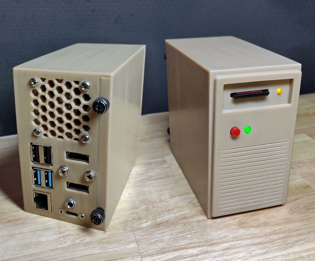
A retro style beige Raspberry Pi 4 tower case. It has a working power button, LED, and IO activity LED. The SD/microSD card can be inserted like a floppy disk to swap between different operating systems. It also has 2 HDMI ports, audio jack, and USB-C power on the rear of the case. There is space for a 40mm exhaust fan and a 40mm or 50mm front intake fan. There is also enough space for a large cooler like the ICE tower. NOTE: There is now a slightly improved V2 of the case. Changes: Added version of case that is 1.5cm taller Increased hole size for push button Added hex cutout to use the included nut for a push button Moved wall ridges to prevent interference with tall connections on GPIO #Parts needed (links at the end): Micro SD to SD Card extender: 1 Micro HDMI to HDMI Adapter Cable: 2 Panel-Mount USB-C Extention Cable: 1 40mm 5V fan (for exhaust): 1 Low-Profile CPU Cooler or ICE Tower Cooler: 1 SPST Momentary Mini Push Button: 1 5mm LED with resistor: 1 3mm LED with resistor: 1 \#6-32 UNC thumbscrew (standard PC case screw): 2 \#6-32 UNC screw or M3 screw (standard PC case screw): 6 various wire/header connectors (for connecting fans/LEDs/power button) Optional: Front 5V 40mm/50mm fan: 1 (note: I've not needed this even when overclocking the Raspberry Pi) Noctua NF-A4x10 to replace CPU Cooler fan: 1 Panel-Mount 3.5mm AUX Male to Female Extension Cable: 1 (note: pre-made cables may be too long and should be shortened.) #Assembly instructions #### Prepare all parts note: any places that require screwing plastic parts together can be replaced with glue if you are way too confident/lazy. * Print out all parts with whatever material/color you would like. * (optional but helpful) Use a thread tap on all screw holes #### Start Assembly * Tap threads for push button. If you don't have a tap, you can use the push button to create the threads. You may need to use a file to help make sure the push button fits if you don't have a tap. * Press fit 3mm LED into the main case. Glue can be added, but the press fit should hold it fine. * Press fit 5mm LED into the main case. Glue can be added, but shouldn't be needed. * Put SD card extender in the SD card tray and attach to the case with screws or glue. This may require a long screw driver that can reach through the fan grill or a very short one that will fit in the case. This is easer to do before anything else is in the way. * (Optional) Attach front fan with screws * Screw/Glue in front panel. Make sure LEDs are visible and the push button does not get stuck. * Put HDMI adaptors in the HDMI holder, but don't mount it in the case. #### Connect wires to the GPIO Header * (Optional) Make a simple splitter for the CPU/Case fan(s). I have the fans connected to 3.3V (pin 1) and ground (pin 9). The fans can use a 3.3V or 5V pin for power and any unused ground. * The push button goes across pin5/pin6 (polarity doesn't matter). * The power LED goes to pin8(+) and pin14(-). * The GPIO LED goes to pin37(+) and pin39(-). * Connect all wires, connectors, and micro SD card extender to the raspberry pi before carefully placing it in the case. At this point all cables/extenders should be connected to the Raspberry pi, but not the case. (note: if using the ICE or low profile heatsinks, they should not be attached at this point) #### Finish Assembly * Use the brass spacers/mounts/standoffs from the cooler to screw the Raspberry PI to the case. These 4 brass pieces should now be going through the Raspberry Pi's mount points into the case. * Add thermal paste or the thermal pad to the processor and attach the CPU cooler with the included screws. * Screw in the HDMI Holder. * Screw in the USB-C extender * Screw in the Audio jack * Attach the rear exhaust fan. * Slide the side panel on and add thumb screws #### config.txt setting * (Optional over clock setting -- Use at your own risk) \# overclock arm_64bit=1 hdmi_enable_4kp60=1 over_voltage=15 arm_freq_min=100 arm_freq=2350 gpu_freq=750 gpu_mem=512 * Enable GPIO LED and IO activity LED \# Additional overlays and parameters are documented /boot/overlays/README dtoverlay=act-led,gpio=19 enable_uart=1 * Enable the power button: https://github.com/Howchoo/pi-power-button https://smile.amazon.com/gp/product/B07YHN83NJ or https://smile.amazon.com/gp/product/B06X3Y4BBB https://smile.amazon.com/gp/product/B07K21HSQX https://smile.amazon.com/gp/product/B075R7QBQD https://smile.amazon.com/gp/product/B00NEMGCIA https://smile.amazon.com/dp/B07V35SXMC or https://smile.amazon.com/dp/B07ZV1LLWK https://smile.amazon.com/dp/B075LDGHHS/ or any similar button https://smile.amazon.com/dp/B08G4WXFX1/ or https://smile.amazon.com/dp/B08G4XC341 https://smile.amazon.com/dp/B07X622RJN or (preferably) make your own. https://smile.amazon.com/gp/product/B08R9KN46J (these fans work well, but are a bit loud even at 3.3V) https://smile.amazon.com/gp/product/B07CQPJJXY or https://www.walmart.com/ip/3ft-3-5mm-Mini-Stereo-TRS-Male-to-Female-Panel-Mount-Extension-Cable/248859634 or make your own https://smile.amazon.com/dp/B01C3RFHDC Although this case was made from scratch, I was inspired by this case by nilly667: https://www.thingiverse.com/thing:4362798
With this file you will be able to print Raspberry Pi 4 case - Retro tower desktop with your 3D printer. Click on the button and save the file on your computer to work, edit or customize your design. You can also find more 3D designs for printers on Raspberry Pi 4 case - Retro tower desktop.