Raspberry Pi 7" Handheld Tablet
thingiverse
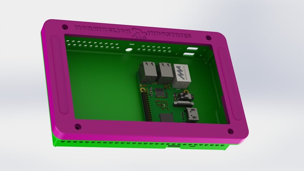
So here is the tablet version of the Rasptop 2.0 and it uses all the same parts except no keyboard and one less USB port. The system fits on a single board with a DC power input and a battery connection. I am planning to use this in my next project, a portable Raspberry Pi 4B device. The board has four main components: a 2S 7.4V Power System, a 9 volt 5amp Power Supply, a Small MOSFET Module, and a DC Barrel Jack. The battery pack will be connected to the system using a DC power input and the charger indicator will show when it's charging. The wiring is straightforward: connect positive from one cell and negative from the other to the B+ and B- tabs on the balance board, then attach the leftover positive and negative wire together making a series connection. The P+ and P- from the balance board go to the MOSFET input side where you also attach the positive and negative from the charger board. You need a wire from Battery + to go to the switch as well, this can be 24ga or even smaller, and the wire coming back from the switch goes to the input signal on the MOSFET module. On the output of the MOSFET module connect the battery level indicator and the DC to DC converter board so they come on when the switch is on. I set the voltage before connecting anything to the DC to DC converter to 5.1 volts, no more than 5.2 volts. I also put the Micro USB in still and just wired it directly to the 5v side of the system so I can plug power in there and not use the battery to run it on the bench or something. In a test with Ubuntu 18.04 MATE and Chromium browser running Google Play Music, I got 14.5 hours of battery life on a full charge playing over Bluetooth speakers and doing other random things on this battery arrangement.
With this file you will be able to print Raspberry Pi 7" Handheld Tablet with your 3D printer. Click on the button and save the file on your computer to work, edit or customize your design. You can also find more 3D designs for printers on Raspberry Pi 7" Handheld Tablet.