Raspberry Pi 7" Touchscreen Super Awesome Portable
thingiverse
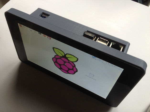
UPDATE: The original model was optimized for a 0.35 nozzle printer, but it sliced poorly on my friend's 0.4 nozzle printer due to thin walls. To fix this, I've uploaded alternate .stl files with a 2mm wall thickness. The same brackets work with either design. A Raspberry Pi is great as a portable Linux machine, but managing it without a display can be tough. Now that the 7-inch touchscreen makes it easy to see what the Pi's doing, things are much better. Some good case designs were already available, but none allowed for easy SD card access, and some couldn't fit onto my 200mm printer. This project was inspired by two existing designs on Thingiverse, but it's a brand new creation hand-crafted with OpenSCAD. Design Goals: 1. Full access to all Raspberry Pi 2 or 3 Model B ports, including the SD card slot. The case covers the USB power input port on the Pi so you don't try to use it by mistake. 2. Room inside for a large battery pack. I'm using a 6000 mAH battery pack. 3. Can be printed without supports - short bridging required. Prints can be made on a 200mm print bed. 4. All cables exit through the side or rear of the enclosure to allow it to sit smartly on edge during use. Ingredients: The circuit I used was published by Adafruit. I used the element14 7-inch Touchscreen and the Adafruit PowerBoost 1000C lipo battery charger with a Raspberry Pi 3B, along with a 6000 mAH 3.7v lipo pack. You'll also need a SPST or SPDT slide switch, some velcro, and a few small (#0 or M3) screws to hold everything together. NOTE: If you try to turn on the Raspberry Pi without a formatted OS loaded onto the micro SD card, the monitor won't turn on. For additional build instructions, see the excellent Adafruit page describing the original project: https://learn.adafruit.com/7-portable-raspberry-pi-multitouch-tablet/overview Print Settings Printer: Velleman K8200 Rafts: No Supports: No Infill: 30% Notes: Designed to eliminate overhangs and minimize bridging. Assembly Steps: 1. The brackets have a set of larger holes on one leg. Use these larger holes and four short M3 screws to connect the surround and both brackets to the back of the screen. 2. Use two of the jumper wires from the Touchscreen kit to connect 5v and GND on the video controller to pins 2 and 9 on the Pi GPIO connector, as per the Adafruit circuit diagram. 3. Cut one end off of the remaining two jumper wires and solder them into the 5v and GND outputs from the PowerBoost 1000C. Connect the other ends to pins 4 and 6 of the Pi GPIO connector, as per the Adafruit circuit diagram. 4. Use four small wood or sheet metal screws to attach the case bottom to the angle brackets, taking care not to damage any internal components - especially the battery. Always shut down the Pi through the menus or command console before turning off the power with the slide switch. Failing to do so may corrupt or damage your SD card.
With this file you will be able to print Raspberry Pi 7" Touchscreen Super Awesome Portable with your 3D printer. Click on the button and save the file on your computer to work, edit or customize your design. You can also find more 3D designs for printers on Raspberry Pi 7" Touchscreen Super Awesome Portable.