Raspberry Pi 7in Touchscreen Enclosure
prusaprinters
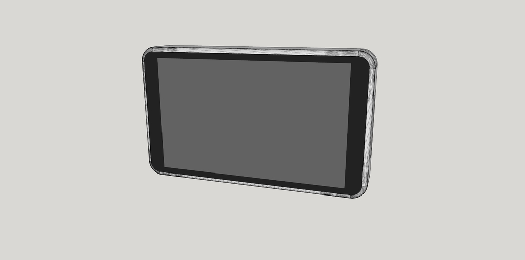
<p>Turn your Raspberry Pi 2 and Raspberry Pi 7" Touchscreen into a completely custom tablet.</p> <p><em>This design is still a work in progress. Cable lengths and required hardware have not been tested/determined.</em></p> <p><em>Work is still on going to find a fitting battery to go inside.</em></p> <p><strong>Features</strong></p> <ul> <li>Ability to mount the Screen to the shell without the use of glue on your screen.</li> <li>Off center mounting location for Raspberry Pi for a larger empty area.</li> <li>USB & Ethernet external access</li> <li>GPIO external access (optional plug)</li> <li><p>Pi Camera mount on back (optional dummy plug) This design is derived from <a href="https://github.com/MCMElectronics/Raspberry-Pi-Tablet">MCM Electronic's Raspberry Pi Tablet shell</a>.</p> <h3>Print Settings</h3> </li> </ul> <p><strong>Rafts:</strong></p> <p>Doesn't Matter</p> <p><strong>Supports:</strong></p> <p>Yes</p> <p><strong>Resolution:</strong></p> <p>0.1mm</p> <p><strong>Notes:</strong></p> <p>If you cannot print at 0.1mm resolution, it should still work. You will have to sand and trim the pieces though.</p> <p>Print List:</p> <ul> <li>Shell</li> <li>Pi Plate</li> <li>Back Plate</li> <li><p>GPIO Plug +<em>Optional</em> if you don't use the GPIO</p> </li> <li><p>Camera Insert<em>or</em> Camera Dummy Plug</p> <ul> <li>Print the dummy plug only if you are not using the Raspberry Pi Camera</li> </ul> </li> <li><p>Mount Frame</p> <h3>Post-Printing</h3> </li> </ul> <p><strong>Finishing</strong></p> <p>Test fit all pieces together. Depending on printer settings and resolution, pieces may need to be sanded or shaved down slightly.</p> <p><strong>Display Adapter Board</strong></p> <ol> <li>Start with all components disassembled, as received originally.</li> <li>Connect the display ribbon cable to the back of the Adapter Board.</li> <li><p>Set the Adapter Board onto the back of the display then connect the touch screen ribbon cable.</p> <ul> <li>See the official <a href="https://cdn.shopify.com/s/files/1/0174/1800/files/how_to_assemble_the_rpi_touchscreen_display.jpg">Build Instructions</a> if you need more information.</li> </ul> </li> <li><p>Use the four (4) screws to attach the Adapter Board to the back of the display. <strong>Raspberry Pi</strong></p> </li> <li><p>Place the Raspberry Pi in the Pi Plate.</p> </li> <li>Use M3 x 5mm sheet metal screws to affix the Pi in place. <ul> <li>Screw type is not yet tested</li> </ul> </li> </ol> <p><strong>Display</strong></p> <ol> <li><p>Place the Shell face up.</p> <ul> <li>Camera cut out against the table</li> <li>GPIO port on your right</li> <li>Up is same wall as the Camera cut out.</li> </ul> </li> <li><p>Test fit Mount Point A pieces. These fit over little triangles on the walls.</p> <ul> <li>Two pieces go on either side of the Camera cut out.</li> <li>One piece goes in the bottom left.</li> </ul> </li> <li><p>Glue Mount Point A pieces in place.</p> </li> <li><p>Test fit Mount Point B pieces. Similar fitting points to the previous pieces.</p> <ul> <li>One piece goes on bottom wall.</li> <li>One piece goes on right wall (next to GPIO).</li> </ul> </li> <li><p>Glue Mount Point B pieces in place.</p> </li> <li>Let glue dry.</li> <li>Place Display face down on a soft surface.</li> <li>Flip over the Shell and place on Display. The screen should fit snugly in place.</li> <li>Using three (3) machine screws, attach the Display to the Shell. <ul> <li>The size of these screws has not yet been determined.</li> </ul> </li> </ol> <p><strong>Camera</strong></p> <ol> <li>Test fit the Camera Insert or the Camera Dummy Plug in the Back Plate. The camera piece will be flush with the outside of the Back Plate.</li> <li><p>Glue the camera piece in place.</p> <ul> <li>If you are using the Camera Insert, align the low side of the plug towards the top.</li> <li>If you are using the Camera Dummy Plug, skip the rest of this section.</li> </ul> </li> <li><p>Attach the Camera Module to the Camera Insert with M2 sheet metal screws. These are the same ones that typically come with a servo for attaching items to the servo horn.</p> <ul> <li>The cable from the camera should go to the low side of the plug.</li> </ul> </li> <li><p>Attach the Camera Cable <strong>Electronics</strong></p> </li> <li><p>Place the Shell with mounted Display face down on a soft surface.</p> <ul> <li>GPIO port should be on your left now.</li> </ul> </li> <li><p>(Optional) Attach the camera cable to the Raspberry Pi. This may require the Back Plate to sit half on the Shell.</p> </li> <li><p>Attach the DSI ribbon cable to the Raspberry Pi.</p> <ul> <li>See the official <a href="https://cdn.shopify.com/s/files/1/0174/1800/files/how_to_assemble_the_rpi_touchscreen_display.jpg">Build Instructions</a> if you need more information.</li> </ul> </li> <li><p>(Optional) Insert the GPIO Plug in the GPIO hole on the Shell.</p> </li> <li>Insert the Pi Plate with mounted Raspberry Pi in its slot in the bottom left of the Shell.</li> <li>Attach the other end of the DSI ribbon cable to the Display Adapter.</li> <li>Use one (1) M4 x 15mm sheet metal screws to affix the Pi in place. <ul> <li>Screw type is not yet tested.</li> </ul> </li> </ol> <p><em>Instructions for Power systems coming soon</em><br/> <strong>As of now, you must run your power lines in via the GPIO hole.</strong></p> <p><strong>Final Assembly</strong></p> <ol> <li>Place the Back Plate on the Shell.</li> <li><p>Use three (3) M4 x 15mm sheet metal screws to affix the Back Plate to the Shell.</p> <ul> <li>Screw type is not yet tested.</li> </ul> <h3>Notes</h3> </li> </ol> <p><strong>Future Changes</strong></p> <ul> <li><p>Internally mounted battery</p> <ul> <li>The plan is to use <a href="https://www.adafruit.com/products/2465">PowerBoost 1000</a> and a <a href="https://www.adafruit.com/product/328">LiPoly Battery - 2500mAh</a>. Once I get the parts, I'll set up the mounting system.</li> </ul> </li> <li><p>Insert for PI/Display power connection access <strong>Updates</strong></p> <p>2015 October 23</p> </li> <li><p>Created mounting frame to replace individual mount points</p> </li> <li>Adjusted mounting hole locations</li> <li><p>Increase wiggle room on mounting system 2015 October 05</p> </li> <li><p>Redesigned shell and mounting points to require less support.</p> </li> <li>Modified Pi Plate to add screw point.</li> <li>Modified Shell to better fit the Raspberry Pi Screen.</li> <li>Added new Mounting Point components.</li> <li>Modified Back Plate screw hole locations for new mounting system.</li> </ul> Category: Tablet
With this file you will be able to print Raspberry Pi 7in Touchscreen Enclosure with your 3D printer. Click on the button and save the file on your computer to work, edit or customize your design. You can also find more 3D designs for printers on Raspberry Pi 7in Touchscreen Enclosure.