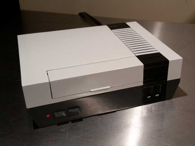
Raspberry Pi B+ Mini Classic NES case.
thingiverse
Warning: Although the Raspberry Pi 3 will fit in this case comfortably the Motorola-SPN5356A that I recommended earlier will not supply enough current for it. I recommend you look for an updated power solution or use touxiong's remix. I plan to update this model for a more available and standardized power supply when I get the time. Thanks! Update: Version 1.1 Fixed proportions, added a card access door, reduced floor thickness of top and bottom pieces(also reduces print time), increased bulk of cable strain relief, dropped power supply holder a few mm, added cartridge carriage(optional, experimental), added integrated supports for top and bottom, various small improvements and cleanup. Version 1: A miniature Nintendo Entertainment System(NES) case for raspberry pi B+ complete with working front power/reset buttons and power indicator LED. Honest efforts were made to remain true to the original NES proportions and appearance(only 55% smaller). This project is not for the faint of heart. Expect frustration. Some basic electronics knowledge and additional parts are necessary for complete design. For best results the raspberry pi board will need to be physically altered. Print Settings Rafts: No Supports: No Resolution: 100 micron layers recommended. Infill: 15%-20% Notes: All parts should print without supports(supports are provided where needed). This animal WILL warp if not adhered to the build platform properly. Consider yourself disclaimed. Use of helper disks on corners recommended to minimize warping on FDM printers. The provided helper disk has a hole in it for the bottom screw holes. After printing gently break off integrated supports from top and bottom pieces. Post-Printing Parts list Raspberry Pi Model B+ Motorola-SPN5356A usb wall charger Radioshack Toggle SW Model #: 275-1565 | Catalog #: 2751565 (power button) Radioshack N.O. momentary SW Model #: 275-1566 | Catalog #: 2751566 (reset button) 5mm red LED 330 Ohm or so Resistor(matched to above LED for it's power requirements) Paperclip(or similar wire for hinge) Superglue Small heat shrink tube(plus heat gun or similar to shrink it) Desoldering Station/Solder/Soldering iron Asus Bluetooth Dongle(for wireless controllers) Model # USB-BT400 2 conductor appliance power cord 24 gauge insulated wire(or some old scrap ethernet cable) A zip tie USB Cable(to breakout USB header) Hot Glue Gun(with glue sticks) 9 X #4 X 3/8" machine screws Instructions Warning! This is an advanced project. Print all parts, sand, then paint, then glue. Cable Strain Relief should preferably be printed with a flexible/rubber plastic. Assemble parts using the posted images as a guide. The vent slides on to the top half(light grey) of the case. The black bezel pieces are glued to the halves of the case. The reason why I separated these pieces instead of printing them monolithic is because it makes the paint job look better. I wet sanded the print with 300 grit sandpaper. Primed with plastic compatible primer and spray painted with the closest matching NES grey colors I could find(a brand of tractor paint seemed pretty close). A small section of a common paperclip can be used for the door hinge. (Optionally you can just glue the door on since it serves no real purpose.) One of the USB headers on the raspberry pi motherboard will need to be turned into a breakout(desoldered and attached to a short cable) and run to the front of the unit. You could devise your own replacement method for this or skip the USB front panel feature all together. The reset pins on the raspberry pi b+ board are missing from the factory and will need to be soldered on. Consult the raspberry pi documentation for more info. The power supply I used was a Motorola SPN5356A USB wall charger which are fairly ubiquitous. Gently crack the case on the unit in a bench vise and remove the power supply board. Desolder the USB connection(this is the +5V output) and the AC power input connections(looks like stiff narrow metal loops). A holder has been provided of the required dimensions for the PS board on the print. Slide appliance cord through the printed strain relief and heat shrink tubes. Solder the cord to the power supply AC input(not polarized) and shrink the heat shrink over the cord near the board with a heat gun. Zip tie the utility cord to the bottom of the case on the provided attachment point. Hot glue a couple of corners on the power supply board to the case to hold it in place. I'm not going to explain wiring the power circuit/switches or calculating the resistor for the LED. It should be fairly obvious to anyone who's tinkered with simple electronic circuits. The raspberry pi b+ board can be powered via it's GPIO pins which is what I did. Consult the raspberry pi documentation for the B+ model for more information. The switch carriage is designed to hold the Radioshack switches in the parts list. Once the switches are in place at the correct operating distance the carriage can be superglued down to the bottom of the case. Some scrap heat sink material was available to me(seen in the picture). My friend milled a few heat sinks to the correct shape for this project. These are just in case the chips got toasty and most likely aren't needed. I'll post more complete instructions if/when I get time. How I Designed This Designed with Blender.
With this file you will be able to print Raspberry Pi B+ Mini Classic NES case. with your 3D printer. Click on the button and save the file on your computer to work, edit or customize your design. You can also find more 3D designs for printers on Raspberry Pi B+ Mini Classic NES case..