Raspberry Pi Electronics Enclosure with Arduino Mega or Rambo Mini and 7" HDMI TouchScreen Display
thingiverse
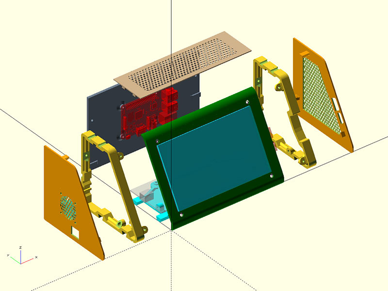
**05/07/2018** I updated the OpenSCAD file to include a 1.5mm base under the electronics board. This added protection for the electronics underneath was deemed more important than saving plastic. The module I added to the OpenSCAD code is Bottom_Flat() for those interested in that. **09/09/2017** I added a vented top option for passive heat release. **DD_2_TopPlate_Vented_Elec_Pi_HDMI7_Rev150.stl** or **DD_4_TopPlate_Vented_Elec_Pi_HDMI7_Rev150.stl* I also updated the solid top plate version to have less plastic in the middle, cutting down on print time. **DD_2_TopPlateBlank_Elec_Pi_HDMI7_Rev150.stl** or **DD_4_TopPlateBlank_Elec_Pi_HDMI7_Rev150.stl*. Use the clearance size that works for you. This is a remix of the Combo Electronics case https://www.thingiverse.com/thing:2466915 to house the raspberry Pi & the HDMI 7" touchscreen (https://www.adafruit.com/product/2407) instead of the LCD displays. Mike Baier asked if I could do this & he beta tested it. I thought it was a good project to test how well this design worked for customizing. In this process, I did change a couple of ways I was doing the faceplate cutouts & reflected those changes back to the previous design. Mike Baier had one problem with the display sticking out too far & think I fixed that with the setback display supports on the bracket, but that is untested since I do not have this display. Since there are so many parts & options, I put all the STL files into 1 file & you will have to split them out with your slicing program. I use the Slic3r Prusa Edition to do this. https://github.com/prusa3d/slic3r/releases I would suggest you print the test print **DD_2_TestSizes_Elec_Pi_HDMI7_Rev148.stl** to see how well the parts fit together. If they are too tight, print the **DD_4_TestSizes_Elec_Pi_HDMI7_Rev148.stl*. You can delete the bracket on your 2nd test print as those connections stay the same. The DD_2 has a clearance of .25mm for the dovetails & the DD_4 files have a clearance of .4mm. Once you are happy that the test parts fit together for you, I would then print the faceplate to make sure that fits & your display fits that & the left bracket. The right bracket should be your next print. If those fit well, the rest should also since the other parts have been tested. I made one file of shim spacers from 1mm to 6mm. Since that is such a small file, I would just print all of those to see which sizes fit best for you. Mike Baier used the 6mm, but you might also need another set of shims with the setback display supports. Here are his beta test photos of the remix: https://www.thingiverse.com/thing:2466915 You can either put the raspberry Pi on the inside back or outside using an additional vesa mount: https://www.thingiverse.com/thing:795786 or the **Raspi7inch_Case.stl** & **Raspi7inch_Lid.stl** https://www.thingiverse.com/thing:1585924 Reference Parts used: I took the dimensions for the Display cutouts from: https://www.thingiverse.com/thing:1585924 I used the raspberry Pi model from: https://www.thingiverse.com/thing:412639 The arduino & fan I got from thing 820960 which does not seem to be there anymore. I increased the height of this by 25.5mm & the width by 14.5mm from the original design to accommodate the larger display. The faceplate is the longest part at 194.6mm which should barely fit on an 8" print bed. For further info on this design, refer to https://www.thingiverse.com/thing:2466915
With this file you will be able to print Raspberry Pi Electronics Enclosure with Arduino Mega or Rambo Mini and 7" HDMI TouchScreen Display with your 3D printer. Click on the button and save the file on your computer to work, edit or customize your design. You can also find more 3D designs for printers on Raspberry Pi Electronics Enclosure with Arduino Mega or Rambo Mini and 7" HDMI TouchScreen Display.