Raspberry PI (OctoPI) Controlled Power Console for 3D Printer
prusaprinters
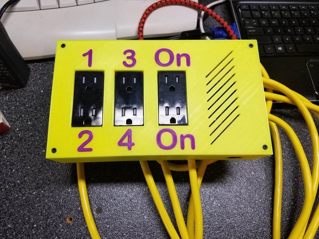
<p>I wanted to make a power control box similar to the one built by Jeffeb3 (<a href="https://www.thingiverse.com/thing:1428478">https://www.thingiverse.com/thing:1428478</a>) to control my Prusa i3 and lighting via OctoPi, however I wanted to use all 4 relays on the Sainsmart relay control board, and also wanted 2 always-on outlets. I also did not want to colocate the Raspberry PI 3B inside the power board, instead opting for repurposing a CAT5 cable to carry TTL signals from the Pi to the power control box. All of my code was based on Jeffeb3's work, please look at his Thing for completing that portion of the build (just duplicate commands for the other 2 relays.)</p> <p>The power control box was designed in FreeCAD. This was my first time designing something in FreeCAD, any constructive feedback is welcome.</p> <p>The Sainsmart relay board is secured to the bottom of the box with 4 M3x5 screws. The top is secured with 4 M3x10 screws. I had to use a drill to ream out the holes to get a better fit, the uploaded design incorporates changes that should make this unnecessary.</p> <p>The power cord was purchased from Lowes, and is a 14/3 cord. I used a drill to open up the power cable hole to match the size of the cord. It is secured in place with two-part epoxy. If I were to do it again I would build in some strain relief into the bottom section of the box.</p> <p>Internal wiring was a mix of 16 and 18 gauge wire which I had on hand. The TTL signals are carried by jumper wires with Dupont connectors on one end.</p> <p>The top was printed in two phases by pausing the print and swapping filament in my Prusa i3 Mk2.</p> <p>Matching up the GPIO outputs from the OctoPi to the wires in the power control box took longer than it should have and quite a bit of trial and error. Turns out the cable was labeled as a 568B cable, but it was actually a 568A cable. I used Dupont connectors to connect to the OctoPi. (<a href="https://acuitysupport.zendesk.com/hc/en-us/article_attachments/203181108/T568-1.png">https://acuitysupport.zendesk.com/hc/en-us/article\_attachments/203181108/T568-1.png</a>)</p> <p>Parts used and links to them are below.<br/> Jumper Wires: https://smile.amazon.com/gp/product/B01L5ULRUA/ref=oh\_aui\_detailpage\_o04\_s01?ie=UTF8&psc=1<br/> RJ45 Connector: https://smile.amazon.com/gp/product/B00IO3HB2K/ref=oh\_aui\_detailpage\_o01\_s00?ie=UTF8&psc=1<br/> Dupont Crimp Connectors: https://smile.amazon.com/gp/product/B014YTPFT8/ref=oh\_aui\_detailpage\_o00\_s00?ie=UTF8&psc=1<br/> Crimping Tool:https://smile.amazon.com/gp/product/B00OMM4YUY/ref=oh\_aui\_detailpage\_o00\_s00?ie=UTF8&psc=1<br/> Sainsmart Relay: https://smile.amazon.com/gp/product/B0057OC5O8/ref=oh\_aui\_detailpage\_o05\_s02?ie=UTF8&psc=1</p> <h3>Print instructions</h3><h3>Category: 3D Printer Accessories Summary</h3> <p>The top was printed in two phases by pausing the print and swapping filament in my Prusa i3 Mk2.</p> <p>Printed in PLA, 0.2mm layer height, no supports.</p>
With this file you will be able to print Raspberry PI (OctoPI) Controlled Power Console for 3D Printer with your 3D printer. Click on the button and save the file on your computer to work, edit or customize your design. You can also find more 3D designs for printers on Raspberry PI (OctoPI) Controlled Power Console for 3D Printer.