Raspberry Pi Zero W Security Camera
thingiverse
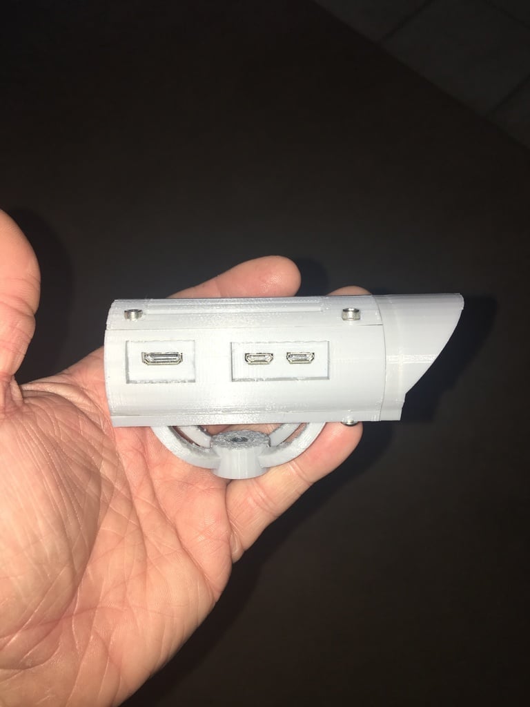
Im not the greatest at writing up howto's! So please be patient with me! I had a problem with my girlfriends kids with lies and also hurting my daughter so I decided to make up a cheap camera. Plus it doubled as a security camera for the house when away as well. The files will be optimized from 3yourmind with the exception of the top with vents. For some reason, the optimized slices weird in flashprint. I have not printed in ReplicatorG or Simplify3d. I have included the origional and optimized version for both. For this project you will need Printed parts; 1x main body 1x top vents 1x bottom 1x front bezel Ive also included the .py scripts for RED led and GREEN led as downloads. 1x Raspberry Pi Zero W (need built in wifi!) https://www.adafruit.com/product/3400 1x 8GB + Micro SD Card (MAKE SURE ITS COMPATIBLE AND KNOWN TO WORK) I use Samsung 32GB (half yellow and half black) and works GREAT. 1x Raspberry Pi Cam (ebay purchased 5mp with 75 degree fisheye with night vision) (wider angle would be best!) https://www.ebay.com/itm/1080P-Camera-Module-Board-5MP-130-Fish-Eye-IR-Night-Vision-For-Raspberry-Pi/202068425949?epid=582139582&hash=item2f0c377cdd:g:Og4AAOSwR21Zzfdn 1x Raspberry Pi Zero Camera ribbon cable (shorter one it would be better 40mm - 60mm?) https://www.adafruit.com/product/3157 1x Micro tactile momentary switch (reset switch) (through hole type) https://www.ebay.com/itm/CLEARANCE-20-pcs-6-x-6-x7mm-PCB-Momentary-Tactile-Tact-Push-Button-Switch-4Pins/172516258499?_trkparms=aid%3D555019%26algo%3DPL.BANDIT%26ao%3D1%26asc%3D41451%26meid%3D217ef34e4f9e408991457486e4cf1bfa%26pid%3D100506%26rk%3D1%26rkt%3D1%26&_trksid=p2045573.c100506.m3226 1x 30mm fan 5V (important need 5V) (either 7mm or 10mm thick) https://www.ebay.com/itm/30mm-5V-Cooling-Fan-for-Raspberry-Pi-and-RepRap-3D-Printer/142351923704?epid=927595224&hash=item2124d5f9f8:g:9k8AAOSwE0JY9HPE 1x RED 3mm LED (Blinks, but would like to make it only blink when movement is detected) https://www.adafruit.com/product/777 (this is a pack of 25 but you only need 1(source maybe fries?) 1x GREEN 3mm LED (Stays lit showing power on) https://www.adafruit.com/product/779 2x 330 OHM Resistors (for LEDS) Miscellaneous 3mm bolts and 2mm bolts. Some wire and soldering tools. Some small shrink tube 4x 2mm x 8-10mm long hex head bolts (pan or socket) 4x 3mm x 35mm long hex head bolts (pan or socket) (bolts top, main body & bottom) 2x 3mm x 5mm long hex head bolts (pan or socket) (holds one end of the zero down) 4x 3mm x 8-10mm long hex head bolts (pan or socket) (holds front to main body) 4x 3mm x 10 - 12mm long head head bolts (pan or socket) (holds fan to base) 4x 3mm nuts 1x Press in threaded insert. I got these from McFadden Dale Hardware. (I don't have the part number and cant find it on their website.) This will change soon to a new style. First thing you will need to do is drill the holes through the Raspberry Pi Zero W on all 4 corners with a 3mm drill bit. Mount the RPI Camera to the front of the main body using 2mm screws. Youll need to solder 2 wires to the tactile switch, make sure you solder the wires to the correct pins. put small shrink tube to cover the wire/solder/pins of switch, and you can clip the other 2 pins off that you dont use. Make sure the wires are long enough to reach the Pi to the reset pins and solder. Next youll need to solder the fan to the RPI Zero W with RED wire going to pin #4 and BLACK going to pin #6. (This will make the fan run whenever the pi is plugged in) Then you will need to solder a 330 Ohm resistor to the cathode side (negativ) leg on the LEDS, then a section of wire from the resistor out. Make sure to put shrink tube over the resistor and solder connections!! Solder RED wire from the ANODE (Positive side) to connect to pins on the PI. Now you can share the ground's by making a Y connection for the LEDS, I kept it simple and used a seperate ground for each LED. For the RED LED (blinking LED) I connected the Positive (anode) side of LED to pin #13, and connected the Negative (Cathode) side of LED to pin #20. For the GREEN LED (Always On) I connected the Positive (anode) side of LED to pin #11, and connected the Negative (Cathode) side to pin #9. Push the LED's in the position of your liking. I put the RED on the LEFT hole looking AT the camera, and the GREEN in the RIGHT hole. Once all soldering is done, you can now plug in the ribbon cable for the camera and mount the RPI Zero to the main body using 3mmx5mm hex head screws. These will go in the FRONT of the PI near the camera connection. Connect the camera to the ribbon cable and screw the front onto the main body using 4x 3mmx5mm hex head bolts. Press or thread in the threaded insert to the bottom mount.. Once that's all done use the 4 35mm bolts to bolt all 3 pieces together and use the nuts on the bottom to secure it. Install Raspbian Jessie or whatever flavor you like on SD card, make sure you do the normal setup using; sudo raspi-config enable camera, set locale, set timezone, etc etc. You will need to install mjpg_streamer; https://github.com/jacksonliam/mjpg-streamer Once that's installed, you will need to add this into your /etc/rc.local (BEFORE exit 0) LD_LIBRARY_PATH=/usr/local/lib mjpg_streamer -b -i "input_raspicam.so -rot 180 -br 55 -sa 20 -sh 100 -quality 100 -vs -ex night -awb auto" /tmp/stream -o "output_http.so -w /usr/local/www -c YOURUSERNAME:YOURPASSWORD" That will start mjpg_streamer upon boot of your pi zero. Then add these to /etc/rc.local BEFORE exit 0 python /home/pi/red_led_blink.py & python /home/pi/green_led_on.py & sudo iptables -t nat -A PREROUTING -p tcp --dport 80 -j REDIRECT --to-port 8080 #This allows you to connect to port 80, as well as 8080. Then for your /home/pi/red_led_blink.py file nano /home/pi/red_led_blink.py ---- start ---- import RPi.GPIO as GPIO import time LedPin = 13 # pin13 def setup(): GPIO.setmode(GPIO.BOARD) # Numbers GPIOs by physical location GPIO.setup(LedPin, GPIO.OUT) # Set LedPin's mode is output GPIO.output(LedPin, GPIO.HIGH) # Set LedPin high(+3.3V) to turn on led def blink(): while True: GPIO.output(LedPin, GPIO.HIGH) # led on time.sleep(1) GPIO.output(LedPin, GPIO.LOW) # led off time.sleep(5) def destroy(): GPIO.output(LedPin, GPIO.LOW) # led off GPIO.cleanup() # Release resource if __name__ == '__main__': # Program start from here setup() try: blink() except KeyboardInterrupt: # When 'Ctrl+C' is pressed, the child program destroy() will be executed. destroy() ---- end ---- CTRL o (save) CTRL x (exit) Then for your green_led_on.py file nano green_led_on.py ---- start ---- import RPi.GPIO as GPIO import time LedPin = 11 # pin11 def setup(): GPIO.setmode(GPIO.BOARD) # Numbers GPIOs by physical location GPIO.setup(LedPin, GPIO.OUT) # Set LedPin's mode is output GPIO.output(LedPin, GPIO.HIGH) # Set LedPin high(+3.3V) to turn on led def on(): while True: GPIO.output(LedPin, GPIO.HIGH) # led on # time.sleep(1) # GPIO.output(LedPin, GPIO.LOW) # led off # time.sleep(3) def destroy(): GPIO.output(LedPin, GPIO.LOW) # led off GPIO.cleanup() # Release resource if __name__ == '__main__': # Program start from here setup() try: on() except KeyboardInterrupt: # When 'Ctrl+C' is pressed, the child program des$ destroy() ---- end ---- CTRL o (save) CTRL x (exit) Then; chmod 655 red_led_blink.py chmod 655 green_led_on.py Once that's done, reboot your pi sudo reboot Once it comes up your green light should be on and the red light will flash at intervals. You can change the interval in the red script file by changing sleep on and sleep off mine are sleep 1 on and sleep 5 off. So its on for 1 second, then shuts off for 5, then turns back on for 1. etc etc etc. Then just point your web browser to your IP address of your pi Zero, in my case I can use either; http://10.1.1.1 or http://10.1.1.1:8080 (most ISP block 80, so you can get around that by using a dyndns and portmap on your router) These cameras will work with Ispy Surveillance and security software. I have yet to get it working with the one software I love the most.... Active Webcam. As I said I'm not that great with write-ups and how to's. I hope to get better!
With this file you will be able to print Raspberry Pi Zero W Security Camera with your 3D printer. Click on the button and save the file on your computer to work, edit or customize your design. You can also find more 3D designs for printers on Raspberry Pi Zero W Security Camera.