Rasptop 2.0 The Better Raspberry Pi 7" Laptop *Source Files Included* *UPDATED a lot*
thingiverse
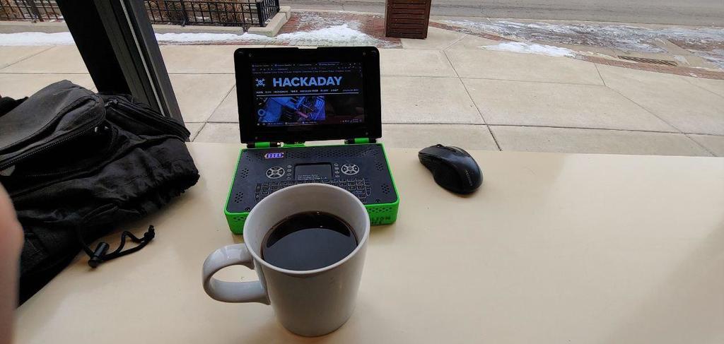
This text appears to be a log of updates and modifications made to a custom laptop build, specifically a Raspberry Pi-based system. The author has been making changes and improvements to the design over time, including adding new features such as a 7-inch touchscreen display, USB ports, and a LiPO battery meter. Here are some specific points mentioned in the text: * The author used a .4mm nozzle for printing parts, but later switched to using a .3mm nozzle. * A pin and socket were added to the center of the palmrest to help hold it down and support it when typing. * A screen bezel was added, allowing the use of a Raspberry Pi Foundation 7-inch touchscreen display at 800x480 resolution. * A custom base for the Up Board was created, which has no SD slot and no micro USB power input. It adds more cooling openings and a USB 3 socket. * The author built an Up board version and uploaded the final files. * A palmrest version using the listed LiPO battery meter was added, with a cutout to fit the meter. * A base modded to hold a RPI 4B was added, with two USB 3 panel mounts in the side. This comes with 7.2v provisions. * The RPI 4B edition was updated to increase vents and height to help cool it. * A year after building the system, the author posted pictures of the Up board version, showing its use as a Windows 10 X64 machine. The text includes several images that show the build process and final result.
With this file you will be able to print Rasptop 2.0 The Better Raspberry Pi 7" Laptop *Source Files Included* *UPDATED a lot* with your 3D printer. Click on the button and save the file on your computer to work, edit or customize your design. You can also find more 3D designs for printers on Rasptop 2.0 The Better Raspberry Pi 7" Laptop *Source Files Included* *UPDATED a lot*.