RC Benchy
prusaprinters
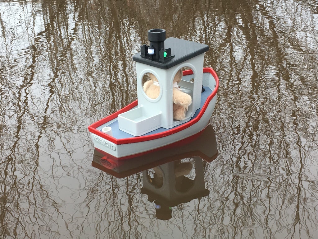
<p>Ever since I printed my first #3DBenchy designed by Daniel Norée arround, I've had the idea of making an R/C version of it.<br/>But I never got inspiration enough to actually do it, until I saw THENOMADSOUL_ (aka KimDIY) post a cool simple but functional RC version of the Benchy.<br/>Now I just had to get started and get my vision realized!</p><p>My criteria for my model was:<br/>1: It has to undoubtedly look like the real #3DBenchy as we all know it, but not necessarily be an exact replica.<br/>2: It has to have the same water line as the original.<br/>3: Be printed on a "standard" 200^3 print volume but still be of reasonable size to be R/C.<br/>4: use cheap and simple components so that anyone can make one for them selves.<br/>5: Actually work..</p><p>So with these critera in mind I started working on it.<br/>This isn't really a remix of the real #3DBenchy, since no dimensions are to scale with the "real" one. This is designed from scratch using the original as a reference.<br/>This is due to the real Benchys dimensions are some what tricky to actually work IRL, lets just say it's top heavy.</p><p>But basically the bow is more vertical than the original, and the hull is a bit wider.<br/>Below the waterline I made the hull as big as possible without looking way too dumb, so there is lots of space for whatever I wanted to put in it, including the obviously needed ballast.<br/>The rest of the model is scaled from the original Benchy dimensions but adapted to fit the new hull shape.</p><p>There are also a couple of versions of it.<br/>You can make the "original one" as a fishing boat, but you can also make a tug boat version that has a tow hook instead of the fish box behind the cabin.<br/>There is also another version of the roof with navigation lights.</p><p>Please read the instructions below for needed hardware and printing and assembling instructions etc.</p><p>And if you make one please share some pictures and/ore videos of it.</p><p>And please, go bananas designing your own accessories for it and so on, I'd love to see what others might do with it.<br/>Perhaps if you have a printer big enough, print a full scale version you can actually ride in yourself?</p><p>Youtube video:<br/> </p><figure class="media"><oembed url="https://youtu.be/JOiXEFOYh3E"></oembed></figure><p> </p><p>Disaclaimer, the pictures and video of the completed boat shows the first functioning prototype.<br/>The design of the hull has changed some since building that one, and I've yet not fully completed building the one posted in these files when posting this, therefore some changes might be done and this is marked as a work in progress.<br/>But I'm confident enough in the design that you can build this boat as it is now. therefore I've made it public.</p><h3> </h3><h3>Print Settings</h3><p><strong>Printer Brand:</strong> Ultimaker</p><p><strong>Printer:</strong> Ultimaker 2</p><p><strong>Rafts:</strong> Yes</p><p><strong>Supports:</strong> Yes</p><p><strong>Resolution:</strong> 0.2</p><p><strong>Infill:</strong> 15%</p><p><strong>Notes:</strong></p><p>All parts fit within a 200x200x200 print volume, and I'm sure you can scale it larger, but probably not smaller.<br/>Printed with 0.4mm nozzle and 0.2mm layer height, 15% infill and 3 perimiters.<br/>Most parts are printed without support, but a few parts require it.</p><p>I used PLA for everything, but I'm sure you can use other materials if you prefer to do so.<br/>Most of my parts were printed on an Ultimaker 2+ and some on an Anet A8.</p><h3>Hardware needed</h3><p>Hardware needed:<br/>Propeller shaft: 4mm diameter 10 cm long, with a sleve that is 5 cm long and 9.5 or 8 mm diameter (there are two STP-files for the aft hull, one for each sleve diameter) and a 36mm propeller for submerged use (not a high speed propeller).<br/>I used this propeller shaft for mine:<br/><a href="https://www.ebay.com/itm/122982704056">https://www.ebay.com/itm/122982704056</a> (No longer available, but search on Ebay for "4mm RC boat propeller shaft" and you´ll find new adds for the same shaft with the specifications mentioned above)</p><p>With this coupler (4mm to 3.175mm version):<br/><a href="https://www.ebay.com/itm/264384553754">https://www.ebay.com/itm/264384553754</a></p><p>And I've also used this one (the 100x50x4 to 3.17mm version, comes with the coupler):<br/><a href="https://www.aliexpress.com/item/Free-Shipping-4mm-RC-Boat-Shaft-Kit-Motor-Drive-Shaft-Coupler-Propeller-Bushing-Bearings-Spare-Parts/32811012835.html">https://www.aliexpress.com/item/Free-Shipping-4mm-RC-Boat-Shaft-Kit-Motor-Drive-Shaft-Coupler-Propeller-Bushing-Bearings-Spare-Parts/32811012835.html</a></p><p>Don't forget the propeller shaft grease.</p><p>You'll need a 2212 1000Kv Brushless outrunner, available "everywhere" for less than 5$.<br/>One just like this:<br/><a href="https://www.ebay.com/itm/183885702391">https://www.ebay.com/itm/183885702391</a></p><p>You'll need an minimum 10A brushless ESC, with reverse.<br/>I used this one from Hobbyking:<br/><a href="https://hobbyking.com/en_us/hobbykingr-tm-brushless-car-esc-10a-w-reverse.html">https://hobbyking.com/en\_us/hobbykingr-tm-brushless-car-esc-10a-w-reverse.html</a></p><p>You can use basically any 2S Lipo bigger than 1000 mAh for it.<br/>I've used 2S 2700 mAh LIPO in mine with great success.</p><p>And I used this radio system from Hobbyking:<br/><a href="https://hobbyking.com/en_us/trackstar-d-spec-ts4g-2-4ghz-4-channel-radio-system-gyro-integrated-update-version.html">https://hobbyking.com/en\_us/trackstar-d-spec-ts4g-2-4ghz-4-channel-radio-system-gyro-integrated-update-version.html</a></p><p>A mini servo such as HXT-900 for example:<br/><a href="https://hobbyking.com/en_us/hxt900-micro-servo-1-6kg-0-12sec-9g.html">https://hobbyking.com/en\_us/hxt900-micro-servo-1-6kg-0-12sec-9g.html</a></p><p>You will also need about 1-1.3 kg of lead beads depending on your battery size.<br/>I bought it at a local scuba diving store here in Sweden who sells it by the kilo.<br/>Due to the small beads (about 2-3 mm diameter) they are easily placed in the bottom of the hull where it is needed, balancing the boat for leveling and correct displacement. Once the correct amount is placed (making sure you can still mount the motor), you can fix it by gently dropping some epoxy over it.</p><p>You'll also need 8 pcs of neodymium magnets for the cabin/lid.<br/>8 mm diameter 3 mm thick, like these ones:<br/><a href="https://www.ebay.com/itm/Wholesale-N52-Super-Strong-Cylinder-Disc-Magnets-8-x-3mm-Rare-Earth-Neodymium/263064152066?hash=item3d3fd86802:m:mBr8ujWUkYTg8sE9EjaJn_A">https://www.ebay.com/itm/Wholesale-N52-Super-Strong-Cylinder-Disc-Magnets-8-x-3mm-Rare-Earth-Neodymium/263064152066?hash=item3d3fd86802:m:mBr8ujWUkYTg8sE9EjaJn\_A</a></p><p>You'll need about 10 cm long 3 mm brass rod, and a 48 mm long 4mmOD/3mmID brass tube for the rudder shaft.</p><p>Some countersunk M3x6 and M3x8 screws, stainless if possible.</p><p>And if you choose to print with the navigation lights you'll need some 3 mm LEDs in colors red, green and white, and appropriate resistors depending on what battery you use.</p><p>The hull parts and propeller shaft tube etc is glued with epoxy, and some smaller components with CA glue.</p><h3>Printing instructions</h3><p>All parts printed with 0.4 mm nozzle and 0.2 mm layer height.<br/>Due to large areas on most parts, print all parts with 8 mm brim to avoid warping.<br/>The name of each part is named in capital letters below.</p><p>The BOW is a separate piece to minimize the amount of support.<br/>If you have a well tuned printer you might get away with printing this piece without support, but if you are unsure, print with support. Note that the support might be a bit tricky to break off, so don't overdo the support.<br/>Print with the aft flat surface towards the bed.</p><p>The HULL FRONT is printed without the need for support.<br/>Print with the aft surface towards the bed.</p><p>HULL FRONT+BOW ONEPIECE, this piece replaces HULL FRONT and BOW if you want to print it as one piece.<br/>If you have a well tuned printer you might get away with printing this piece without support, but if you are unsure, print the separate pieces that does not require that much support material.<br/>Print with the aft surface towards the bed.</p><p>The HULL AFT is printed without the need for support.<br/>Print with the front surface towards the bed.<br/>There are two versions of this part depending on the diameter of you propeller shaft tube.</p><p>The TRANSOM is printed laying flat on the print bed.<br/>There are three versions of this, one with the nameplate and one without, and one without name plate but with drainage holes.</p><p>The DECK is printed in three separate pieces, DECK1, DECK2 and DECK3.<br/>All pieces printed flat on the print bed.<br/>DECK2 has two break away tabs that are cut off after the deck is glued in place in the hull.</p><p>The RUDDER is printed with the aft (thin) side down.</p><p>The RUDDER SUPPORT is printed with the upper side towards the bed.<br/>You can also make this piece out of aluminum if you want it to be sturdier.</p><p>The BATTERY SHELF is printed with the top side towards the bed.</p><p>The RADIO SHELF is printed with the top side towards the bed.</p><p>The cabin is printed in two separate pieces to avoid tall support structures or long bridges.<br/>And the lower part of the cabin is available in two versions.<br/>Print either CABIN LOW FISH or the CABIN LOW TUG depending on what version you want.<br/>Print the CABIN LOW FISH/CABIN LOW TUG with the bottom towards the bed, using break away support material. Support will only be on not visible areas.</p><p>For the "original" fishing boat version you need to print the FISHING ROD HOLDER.<br/>For the tug boat version you need to print TOW HOOK and TOW HOOK SUPPORT.</p><p>The CABIN TOP is printed upside down, angled (8 degrees) so that the printing layers are parallel with the bottom surface (which is now facing upwards) that will be glued to the lower cabin section, meaning that this part is printed with support.<br/>Or if you don't care about having the layers in different directions on the top and bottom halves of the cabin, you can print it flat on the print bed (but still upside down).</p><p>The ROOF BOARD is printed without support, bottom side down towards the bed.</p><p>The roof is available in two versions, either with or without shelves for navigation lights.<br/>ROOF is the "original" without shelves, and ROOF NAV is the one with, print either one.<br/>This part is printed without support flat on the print bed.</p><p>The navigation lights NAV HOUSE AFT and NAV HOUSE SIDE are all printed with the bottom side towards the bed, Brim not needed on these due to being such small parts, but support is needed due to large overhangs.<br/>Print two of NAV HOSE SIDE, but make one mirrored in the slicer.</p><p>The lenses for the nav light lenses NAV LENS AFT and LAV LENS SIDE are printed in transparent plastic if you want to light them up.<br/>But of course you can also print them in red and green and just let them be without LEDs.<br/>The NAV LENS SIDE is symmetrical and fits both sides, so print two if this.<br/>No support needed.</p><p>The CLEAT is optional, printed bottom side towards the bed.</p><p>The Wheel is printed in two halves WHEEL1 and WHEEL2, and then glued together.<br/>A perfect part for printing in woodfill.</p><p>The STEERING ARM can be purchased at your local hobby shop, these things are used for nose gear steering on RC airplanes, but if you don't want to buy it you can print this piece, and mount an M3 nut in the slot and an M3 screw to fasten it to the rudder shaft.<br/>You might need to ream out the small holes depending on what push rod you'll use.</p><p>The STAND is not necessary for the boat itself, but it is very nice to have booth when working on the model and just for displaying it. It is printed without support, flat on the print bed.</p><h3>Assembling instructions</h3><p>Before gluing anything, dry-fit the pieces and make sure they fit properly, and lightly sand and clean all contact areas.<br/>When gluing, use tape and small clamps to fix the parts during hardening.</p><p>The 4 hull pieces are glued together with epoxy.<br/>In the joint between HULL FRONT and HULL AFT, on the railing there are holes to place pieces of filament to guide thew pieces together.<br/>For the BOW and the TRANSOM the mating parts have ridges that fit in the slots of these pieces, make sure they fit correctly before gluing.<br/>Make sure to cover the entire contact surface with glue to ensure a tight seal.<br/>Epoxy that is squeezed out is wiped off before it hardens.</p><p>Once the hull is glued, carefully glue in the propeller shaft sleeve, make sure not to get any glue in the bearings, I taped the end of the sleeve with masking tape before gluing it in place.<br/>The end of the sleeve shall not protrude outside the hull, it shall be just in line with the hull outer surface.</p><p>The deck is glued in place, start with the mid section, and then the aft section, try to minimize the gaps between them and make sure the joints are properly glued to a tight seal.<br/>Then the front section is glued in place.<br/>Use the cabin as a template to make sure the parts have not shifted.<br/>Once all cured you can cut away the two tabs on the mid section of the deck.</p><p>Glue in place the neodymium magnets in the 4 locations in the deck, and in the 4 locations in the lower cabin part.<br/>These magnets will hold the cabin in place but still makes it easily removed for access, make sure the polarity matches so the magnets don't repel.</p><p>Once this far you can prime and paint the hull if you want.</p><p>Mount the motor using two M3 screws, make sure they don't protrude too long and short the windings in the motor.<br/>Mount the universal joint on the motor, but don't put in the propeller shaft just yet.</p><p>Cut a 48mm long piece of the brass tube, and glue it in place in the aft hull section wehere the rudder shaft is.</p><p>Take the brass rod and bend the end of it 90 degrees to an L-shape where one end is about 8-10 mm long, bend it as sharp as you can.<br/>Glue the rod in place in the rudder, make sure the shaft is properly perpendicularly seated.</p><p>Once dried, trim the length of the rod to 57 mm from the top surface of the rudder.<br/>This should make the shaft protrude enough to mount the STEERING ARM, but not hit the deck from underneath.</p><p>Make a pushrod for the rudder out of piano wire or using propper pushrod linkage and mount it on the steering arm.<br/>Put the rudder in place and mount the steering arm.<br/>This can be a bit fiddly but it is doable, the smaller hands you have the easier it will be of course.</p><p>Once the rudder is in place you can put in the propeller shaft and fasten it to the universal joint. Use thread lock to ensure these will not accidentally come loose.<br/>A 36mm diameter propeller should run freely inside the rudder at all rudder angles.</p><p>Mount the rudder support to the hull using M3x6mm screws.<br/>Then put another M3x6 screw to secure the rudder, but do not tighten it since the rudder will pivot around this.</p><p>Print the parts needed for the cabin, whatever version you choose.<br/>The top and lower half of the cabin are glued together using CA glue.<br/>Prime and paint if you want.</p><p>The roof consists of 2 pieces, these are glued together using CA glue.<br/>If you put navigation lights on it these are also glued using CA glue.<br/>There are holes in the roof prepared for wiring, and also in the cabin wall there is a channel for wiring as well.<br/>In the bottom of this hole in the cabin, a JST male (the one with the pins) fit snugly and can be glued in place, making for a neat installation without loose hanging connectors.<br/>You can also print the Bulkhead light and put in the cabin: <a href="https://www.thingiverse.com/thing:2824413">https://www.thingiverse.com/thing:2824413</a></p><p>The steering wheels two halves are glued together using CA glue, and then glue it in place in the cabin.</p><p>Glue in place the details such as tye cleat and fishing rod holder etc.</p><p>Do not mount the battery shelf just yet.<br/>Mount the servo and ESC and other electronics and ensure they work properly.</p><p>Now it is time to put in the ballast.<br/>How much you need depends on what battery you use and how much your model weighs.<br/>But I needed about 800 g lead beads in front of the motor, just below the battery shelf, and about 150g in each pocket beside the propeller shaft, a total of about 1.1 kg ballast.<br/>Remember to place the battery roughly where it will be placed later on while balancing.<br/>Also remember to have the cabin in place since this will shift the weight forward.<br/>Aim for as low center of gravity as possible since the boat is very tall.</p><p>Once you have the correct amount of ballast in place, fixate it using some thinned down epoxy and gently brush it over over the ballast, this will fixate most of the ballast to prevent it from moving around.</p><p>All up weight of the boat should end up at about 2.1-2.2 kg to have the waterline at the correct level.</p><p>Now you can mount the battery shelf using 4 M3 screws, (this needs to be removable for future access to the motor screws).<br/>The battery is attached to the battery shelf using small pieces of self adhesive Velcro.</p><p>And by now you should be all done, Enjoy your radio controlled fully functioning R/C Benchy :)</p><p>Below are some pictures of the building process of my boats.<br/>Most pictures show the inside without the deck mounted to more clearly show how it's done.</p><pre><code class="language-plaintext"> Youtube videos </code></pre><p>==============</p><p><strong>Here I'll link to videos other makers have made about their RC Benchy builds.</strong></p><p>3D Printing Stuff has started on a video series about his build, sharing his ideas on some awesome light controls and other neat ideas. make sure to subscribe to his channel to follow his build.</p><p>User Rainfly put an Ardupilot autopilot on his RCBenchy and made into a drone :)</p><h3>Other creators mods and accessories for the RC Benchy.</h3><p><strong>Rudder access hatch by simon5492</strong></p><p>Simon5492 created this access hatch for the rudder connection.<br/>Great mod for easier access to the steering arm.<br/>Check it out!<br/><a href="https://www.thingiverse.com/thing:2920472">https://www.thingiverse.com/thing:2920472</a></p><p><strong>Roll stabilizer by RainFly</strong></p><p>RainFly created these fins to put on the hull to stabilize the roll movements.<br/>Check it out!<br/><a href="https://www.thingiverse.com/thing:2985150">https://www.thingiverse.com/thing:2985150</a></p><p><strong>Servo mod for steering wheel</strong></p><p>Lowtus77 made this mod to make the steering wheel "work" by using an additional servo.<br/>Check it out!<br/><a href="https://www.thingiverse.com/thing:2995676">https://www.thingiverse.com/thing:2995676</a></p><p><strong>Lower CG Battery shelf</strong></p><p>Lowtus77 designed this clever battery shelf for lower battery placement.<br/>Check it ut!<br/><a href="https://www.thingiverse.com/thing:3015835">https://www.thingiverse.com/thing:3015835</a></p><p><strong>Tie down rails</strong></p><p>Lowtus77 designed these tie down rails to hang accessories from, such as fender tires and other cool stuff.<br/>Check it out!<br/><a href="https://www.thingiverse.com/thing:2995727">https://www.thingiverse.com/thing:2995727</a></p><p><strong>540 size motor mount</strong></p><p>Motsche designed a nice looking motormount for a brushed 540-size motor.</p><p>Check it out!<br/><a href="https://www.thingiverse.com/thing:3526016">https://www.thingiverse.com/thing:3526016</a></p>
With this file you will be able to print RC Benchy with your 3D printer. Click on the button and save the file on your computer to work, edit or customize your design. You can also find more 3D designs for printers on RC Benchy.