RC Dozer Fire Boat
prusaprinters
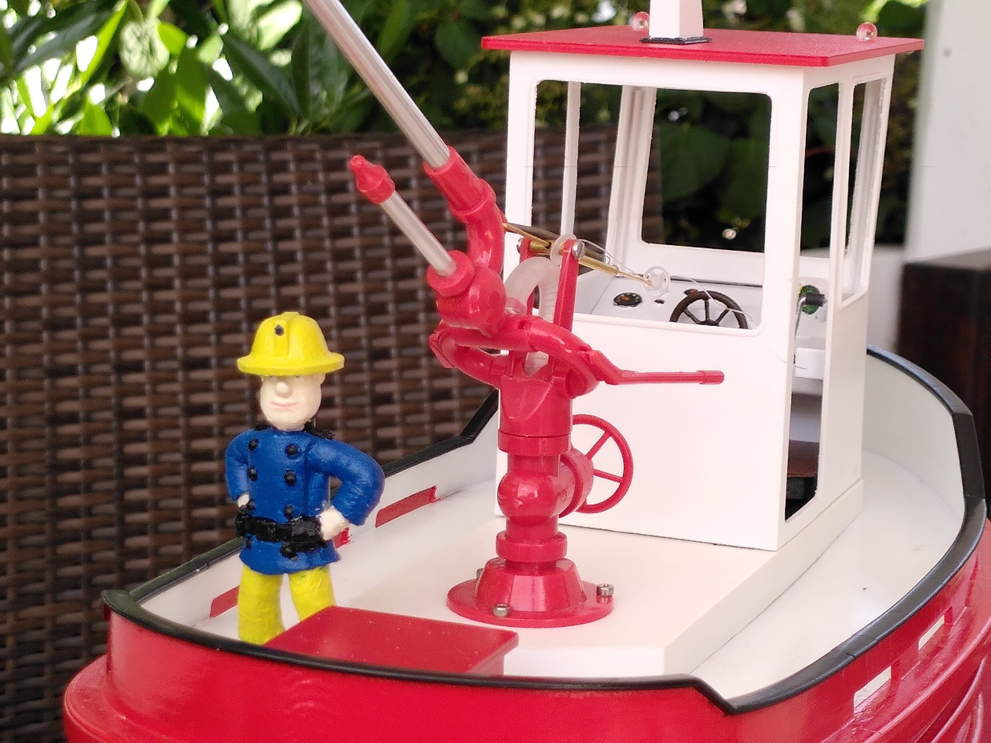
<p>This is an upscaled modified version of the <a href="https://www.thingiverse.com/thing:3052022">RC Boom boat or Dozer boat boot</a> by <a href="https://www.thingiverse.com/rene76">rene76</a> over at Thingiverse. With a functioning RC fire monitor and RC-controlled water pump installed, it brings some action to the pool.</p><p>Major changes as compared to the original model:</p><ul><li>Scaled to 150% to provide enough space for the fire monitor and a water pump</li><li>Improved motor stand with extension to fix the stern tube in position, helps in axes alignment</li><li>A modified deckhouse base moves the wheel house to the front, makes room for the fire monitor and houses the actuating servos</li><li>New hollow mast with room for mounting LEDs </li><li>Raised wheel house floor that covers LED cables and accommodates magnets to keep the captain in place</li></ul><p>Featuring:</p><ul><li><a href="https://www.thingiverse.com/thing:3536817">Fireman Sam</a> by <a href="https://www.thingiverse.com/VidovicArts">VidovicArts</a> (Thingiverse) scaled to 75 mm height</li><li><a href="https://www.thingiverse.com/thing:2952303">Rettungsring</a> (life ring) by <a href="https://www.thingiverse.com/StephanBodensee">StephanBodensee</a> (Thingiverse)</li></ul><p>The complete model weights in at around 1.2 kg and draws roughly 4.5 cm of water (6 including the nozzle).</p><p>Have fun building this model, and thank you for sharing your make!</p><p><i>Note that the pictures were taken at various stages of the build and are not always necessarily in the right chronological order. </i></p><p> </p><h3>Additional (non-printable) parts used in this model</h3><p><i>Please note I am only listing what I have used for this specific model. I am not in any way affiliated with any of the manufacturers nor is any of this in any way sponsored. Feel free to choose alternatives as you see fit.</i></p><ul><li>Remote with at least 5 channels (e.g. FlySky FS-GT5 with FS-BS6 receiver)</li><li>Motor: MAX Power 400</li><li>Shaft M4x130 with 90 mm stern tube (Stevenrohr 90+Welle M4x130 mm)</li><li>Shaft coupling 2.3 / 4 mm (Wellenkupplung 2,3 auf 4 mm)</li><li>3x Servo MG90S</li><li>Brass rods and tubes</li><li>ROMARIN Fire Monitor 1/25th scale</li><li>ROMARIN Control Disc Set</li><li>Waterpump: Search for “Zahnradpumpe Wasserpumpe Pumpe selbstansaugend”</li><li>LEDs: <ul><li>2x clear blue 8mm ultra-bright LED (wide-angle, lensed)</li><li>2x clear white, 4mm, wide-angle, lensed (SSL-LX5093UWW) with red and green filter<br>alternative: 1x red and 1x green ultra-bright 5mm LED, lensed</li><li>1x clear white, 5mm, cylindrical (VAOL-5701WY4)</li></ul></li><li>ESC and some PPM controlled switch to control the water pump. I've used a custom arduino-based solution that also controls the navigation and emergency lights, but that is a different story…</li><li>7.4V 2S LiPo battery; for beginners like me, I also recommend a LiPo monitor with low-voltage-alarm that really can save a battery's life</li></ul><p> </p><h3>Build Instructions </h3><p>This model uses several parts from the original <a href="https://www.thingiverse.com/thing:3052022">RC Boom boat or Dozer boat boot</a> by <a href="https://www.thingiverse.com/rene76">rene76</a> scaled to 150% (all files that start with “150-”).</p><p>All model files are already in their recommended printing orientation. Unless noted otherwise, no supports are required and 2-3 wall lines at 0.2 mm layer height should be fine. </p><p>Disclaimer: I'm writing these instructions from memory and they will be sketchy at best. Make sure that before cutting or glueing anything, you understand how the model works and how to access parts of the model later on. Do not take these instructions as a guarantee for success.</p><p>That said, a great help to me was the video series by the YouTuber <a href="https://www.youtube.com/c/DerRCModellbauer"><i><strong>Der RC-Modellbauer</strong></i></a>, where he shows how the original model is built, starting with this video:</p><figure class="media"><oembed url="https://www.youtube.com/watch?v=NYm_sCvJ0BA"></oembed></figure><h4> </h4><h4>The Hull</h4><p>Printed Parts:</p><ul><li><code>150-hull1.3mf</code> (3-4 wall lines, with supports)</li><li><code>150-hull2.3mf</code> (3-4 wall lines)</li><li><code>150-hull3.3mf</code> (3-4 wall lines, with supports)</li><li><code>150-hatch1.3mf</code></li><li><code>150-boatstand.3mf</code> (optional, use 4-5 wall lines and thick floor+roof for extra sturdiness)</li></ul><p>Consider printing the hull parts with a larger nozzle size and layer height, this will speed things up considerably.</p><p>During assembly, the boat stand will come in handy, so I recommend printing that while glueing and painting the hull.</p><p>For glueing the hull parts, I recommend using a 2-component glue and clamps. Make sure the parts align properly. Remaining gaps can best be filled with baking soda and superglue (lots of videos on YouTube on this subject). I've used filling primer, lots of sanding and acrylic spray paint to get a watertight hull. The inside should also be water-tight; I've applied a thin coat of fast-curing resin there, which is fine but also a bit messy.</p><h4>The Rudder</h4><p>Printed Parts:</p><ul><li><code>150-nozzle.3mf</code></li><li><code>rudder_arm.3mf</code></li></ul><p>Additional Parts:</p><ul><li>Brass tube (ID 3.1mm, ~57 mm) and rod (OD 3 mm, ~69 mm) </li><li>Adjusting ring (ID 3 mm)</li><li>PTFE washer (ID 3.2 mm)</li></ul><p>Check the build video series mentioned above on how to assemble these parts. </p><p>In a nutshell: The lengths given above are as shown in the cut view of the model. However, I suggest to not initially cut the brass tube and rod to their final length, you can still do that after a fit check. The tube is only glued where it exits the hull and the rod is only glued to the nozzle. Make sure to thoroughly deburr the tube so that the rod can slide and rotate in it without excess friction. </p><figure class="image"><img src="https://media.printables.com/media/prints/197760/rich_content/7b22a4d9-7308-4660-9aec-8f3f3e4f556e/ruderanlage3.png#%7B%22uuid%22%3A%2236d065a4-d069-4af2-b026-b7602cf7708b%22%2C%22w%22%3A1938%2C%22h%22%3A1453%7D"></figure><p>The set ring that mounts the rudder arm to the rod needs to be glued to the rudder arm, the set-crew alone will not do the trick.</p><figure class="image image_resized" style="width:43.75%;"><img src="https://media.printables.com/media/prints/197760/rich_content/c0875aca-4ae2-40f1-a41a-2f1bc58de75b/grafik.png#%7B%22uuid%22%3A%22660bb026-89d8-43e6-bd3d-5dbabcb3d503%22%2C%22w%22%3A564%2C%22h%22%3A748%7D"></figure><h4>Propulsion System</h4><p>Printed Parts:</p><ul><li><code>motor_mount.3mf</code></li><li><code>kardan_protector.3mf</code></li><li><code>axis_guide.3mf</code></li><li><code>propeller-3blade-m4-33mm.3mf</code> (customized from <a href="https://www.thingiverse.com/thing:2431995">RC Boat Propeller (Customizable, defaults for 40mm, M4 nut)</a> by <a href="https://www.thingiverse.com/arnew">arnew</a>, requires support)</li><li><code>file-guide.3mf</code> (optional)</li><li><code>rudder_servo_holder.3mf</code></li></ul><p>The <code>motor_mount</code> is printed in two pieces that need to be glued together. Short pieces of 1.75 mm filament can be used with the guide holes on either part for proper alignment.</p><p>I've used the <code>file-guide</code> to prepare a small brass tube at the right angle to be soldered to the stern tube. This can be used as a grease nipple after assembly and for regular maintenance. For more ease of use, I've extended the grease nipple with a longer tube up to the top of the deck, with its inner diameter matching the syringe used for applying the grease.</p><p>Important note: The outer end of the stern tube must reside outside the nozzle, while the nut between stern tube and the propeller needs to be situated just within the nozzle. This way, the nozzle can be removed at any time by first unscrewing the propeller and then removing the drive shaft. </p><figure class="image"><img src="https://media.printables.com/media/prints/197760/rich_content/84eab805-c159-4f01-a666-530454f3fda1/grafik.png#%7B%22uuid%22%3A%22a2f9d5b7-f42e-4158-823a-abcae38b9037%22%2C%22w%22%3A2106%2C%22h%22%3A628%7D"></figure><p>Use the <code>axis_guide</code> to properly align the shaft and motor axis while glueing the stern tube to the <code>motor_mount</code>. Afterwards, replace the <code>axis_guide</code> with the cardan joint. This method helped me to greatly reduce <a href="https://youtu.be/LBqiCHxAw7s">vibrations in the drive train due to misaligned axes</a>.</p><figure class="image"><img src="https://media.printables.com/media/prints/197760/rich_content/076a5add-2e37-4613-9f03-bc36e8f2696f/grafik.png#%7B%22uuid%22%3A%2273960d07-a5d8-45fb-9639-d3bf22f752ba%22%2C%22w%22%3A2082%2C%22h%22%3A638%7D"></figure><figure class="image"><img src="https://media.printables.com/media/prints/197760/rich_content/dd536395-fb32-43f1-8c6a-813e32bbdb06/grafik.png#%7B%22uuid%22%3A%22bda30a5a-02f9-4ade-9312-93d8c27d3129%22%2C%22w%22%3A2080%2C%22h%22%3A596%7D"></figure><p>For more stability, the motor is secured to the motor mount with one or two cable ties.</p><p>Now the assembly can be glued to the hull, again having an extra eye on the position of the propeller. When mounting the propeller, make sure that the two nuts work together to hold the propeller in position and the set ring is adjusted so there is just enough play for the drive shaft to rotate freely. The drive shaft will be water tight after applying grease trough the grease nipple.</p><figure class="image"><img src="https://media.printables.com/media/prints/197760/rich_content/af42648a-ef63-4859-8123-481f2df246ad/grafik.png#%7B%22uuid%22%3A%2201ca1135-5cd7-415c-8acf-d704c1fa3210%22%2C%22w%22%3A2058%2C%22h%22%3A586%7D"></figure><p>Afterwards, the hull needs to be closed around the stern tube with some putty. </p><p>Now it's also a good time to drill a hole in the hull to glue in a short stub of brass tube as an inlet to the water pump (here, the silicone tube is already connected to it; also note the aluminium extension tube for the grease nipple):</p><figure class="image"><img src="https://media.printables.com/media/prints/197760/rich_content/0201bbfa-5fbd-4a87-9fc9-aecd02c6905f/grafik.png#%7B%22uuid%22%3A%227400eab5-0ac5-44d2-9f3e-1254c1addf35%22%2C%22w%22%3A2718%2C%22h%22%3A1174%7D"></figure><p>Finally, the holder for the rudder servo is glued to the hull (the servo is installed afterwards so that the cables are not at risk of also being glued to the hull):</p><figure class="image"><img src="https://media.printables.com/media/prints/197760/rich_content/12dd59f2-4e8e-4f40-9d1c-224c66f28346/grafik.png#%7B%22uuid%22%3A%22fe665145-ff4a-4196-a2d3-e4ffa67e616a%22%2C%22w%22%3A1840%2C%22h%22%3A920%7D"></figure><p>Obviously, the servo needs to be connected to the rudder arm with a rod.</p><h4>Fire Monitor</h4><p>Printed Parts:</p><ul><li><code>deckhouse_base.3mf</code></li><li><code>washer_15x7x1.3mf</code></li><li><code>rivet_guide.3mf</code></li></ul><p>For installation of the fire monitor and control disc set, refer to the manufacturer's instructions. Note that the bore in the <code>deckhouse_base</code> that takes the rotating shaft of the fire monitor is intentionally slightly undersized and needs to be widened so that the shaft can rotate without wiggling around. For me, using a drill in reverse worked fine. Checking the progress several times while widening the bore, helps too.</p><p>The rivet (“niet”) which is part of the fire monitor kit should not be soldered to the shaft. Rather, it can be glued to the pulley with the <code>rivet_guide</code> in-between. When tightening the set-screw on the pulley, the rivet can be held at a fixed position relative to the shaft while still allowing for a later disassembly:<img src="https://media.printables.com/media/prints/197760/rich_content/1685ea3f-e134-4a47-ac7b-8fd29c5a3996/firemonitor-schnitt.png#%7B%22uuid%22%3A%222fa6ac05-0c6e-4e4f-bfb8-a10e1e24689d%22%2C%22w%22%3A2044%2C%22h%22%3A1533%7D"></p><p>In the end, it should look something like this:</p><figure class="image"><img src="https://media.printables.com/media/prints/197760/rich_content/c205cd30-4546-47f0-aed8-2ea3e49cae9b/20220618_101848-afp3.jpg#%7B%22uuid%22%3A%22e49eb230-25d5-4a47-b7d4-66b7399d58ec%22%2C%22w%22%3A4000%2C%22h%22%3A3000%7D"></figure><figure class="image"><img src="https://media.printables.com/media/prints/197760/rich_content/770ea81d-a72b-4bd5-843f-ddd46c679bae/20220618_103042-afp3.jpg#%7B%22uuid%22%3A%22a09ab896-233e-4d35-8e5d-903c3a11f2fc%22%2C%22w%22%3A4000%2C%22h%22%3A3000%7D"></figure><p>When connecting the pump between the water inlet and the fire monitor, make sure to have enough silicone tube so that the monitor can still move around without kinking it.</p><p>To place the deckhouse base on the boat, it needs to be tilted sideways so that the huge control disk can clear the opening in the hull. Then push down gently until the base rests flush on the deck. Do not glue the base to the deck, it needs to be removable to access the interior of the boat.</p><h4> </h4><h4>The Wheelhouse</h4><p>Printed Parts:</p><ul><li><code>new_mast.3mf</code></li><li><code>150-radar.3mf</code></li><li><code>new_roof.3mf</code></li><li><code>150-deckhouse2-mod.3mf</code></li><li>2x <code>reflector_navlight.3mf</code></li><li><code>inside_deckhouse_cut.3mf</code></li><li><code>150-steeringwheel.3mf</code></li><li><code>wheelhouse_floor.3mf</code></li></ul><p>Before assembling the mast, solder some extra thin isolated wires to the LEDs (old data cables are a wonderful source for this kind of wire) and test if they work; do not forget the mandatory series resistors. Then, insert the LEDs in the top part o the mast, carefully bending the blue LEDs' pins so that they can be routed down the hollow mid-part of the mast. After more testing and some glueing, it should look something like this:</p><figure class="image"><img src="https://media.printables.com/media/prints/197760/rich_content/7df10437-7c29-43ba-b87e-163ab2819b78/grafik.png#%7B%22uuid%22%3A%22f3d215e2-1b85-4106-a051-9d7d603dd201%22%2C%22w%22%3A1318%2C%22h%22%3A674%7D"></figure><p>At the rear and top of the topmost LED (cylindrical shape), apply some black opaque layer so that the top light is not visible from behind the mast.</p><p><img src="https://media.printables.com/media/prints/197760/rich_content/48c29be2-7735-4104-b0fa-cfeb7f34dded/20220629_125552-afp3.jpg#%7B%22uuid%22%3A%226049592e-8e95-4608-867d-e815a1182d57%22%2C%22w%22%3A4000%2C%22h%22%3A3000%7D">For the navigation lights, apply a metallic paint to the inside of the two <code>reflector_navlight</code> parts to serve as a reflector. Before assembly, make sure that the diodes fit without breaking the delicate part. <a href="https://de.wikipedia.org/wiki/Positionslicht#Farben_und_Sektoren">Navigation lights are red and green</a>, which can be achieved by glueing small pieces of red and green translucent foil over the <code>reflector_navlight</code> open sides.</p><p><img src="https://media.printables.com/media/prints/197760/rich_content/b55342fa-dc52-40ac-83ce-c2e03b3e825f/navlight.png#%7B%22uuid%22%3A%22bfa36d84-3a45-4923-a9e7-5a517d61ee8b%22%2C%22w%22%3A1803%2C%22h%22%3A1359%7D"></p><p>The cables can be routed along the roof and one corner of the deck house:</p><figure class="image"><img src="https://media.printables.com/media/prints/197760/rich_content/b1ec349a-0458-4b3a-97ac-a6325eaf38c4/20220629_125609-afp3.jpg#%7B%22uuid%22%3A%22142b94e5-d49a-4cbc-8cb1-15f50a69e4de%22%2C%22w%22%3A4000%2C%22h%22%3A3000%7D"></figure><figure class="image"><img src="https://media.printables.com/media/prints/197760/rich_content/c833f09e-3f88-46bf-956b-abafd8533805/20220629_125632-afp3.jpg#%7B%22uuid%22%3A%22b59fde51-0ff7-4342-bd37-a17b7d32414a%22%2C%22w%22%3A3000%2C%22h%22%3A4000%7D"></figure><p>Later, the navigation lights will turn on with the rest of the electronics:</p><figure class="image"><img src="https://media.printables.com/media/prints/197760/rich_content/93c1c3ac-76be-450b-8b42-5bfa75783515/5-20220708_085357-g16-img_6435.jpg#%7B%22uuid%22%3A%22e9c4e43c-940b-48c9-a739-8f98c7f4cb8d%22%2C%22w%22%3A3092%2C%22h%22%3A2319%7D"></figure><p>The light controller even supports different operating modes (see subtitles):</p><figure class="media"><oembed url="https://youtu.be/mNOA_ziOYAw"></oembed></figure><p>A few magnets glued below the raised cabin floor provide the captain with a strong hold in rough waters; with the help of some iron washers under the boots: </p><figure class="image"><img src="https://media.printables.com/media/prints/197760/rich_content/a00b738f-8b0c-4996-8854-61f0261bbd77/20220618_110140-afp3.jpg#%7B%22uuid%22%3A%223cfe6e28-bde0-4589-93ef-abafd09156d8%22%2C%22w%22%3A4000%2C%22h%22%3A3000%7D"></figure><p>Assembling the wheel house, the interior and the raised floor while routing the cables through the floor can be a bit tricky; best try this out before applying any glue.</p><h4>Last not Least</h4><p>Printed Parts:</p><ul><li><code>150-grate.3mf</code></li><li><code>150-hatch2.3mf</code></li><li><code>150-exhaust1.3mf</code></li><li><code>150-exhaust2.3mf</code></li><li><code>150-heat-protection-exhaust.3mf</code></li><li><code>150-radar_screen.3mf</code></li><li><code>150-stairs.3mf</code></li></ul><p>While <code>150-hatch1</code> is mandatory to cover the access hatch to the rudder arm, all other parts are optional. Before mounting the exhaust assembly or stairs however, make sure they do not interfere with the mechanics of the articulated fire monitor. For my boat, in the end I decided against permanently installing the exhaust: The RC Dozer Fire Boat runs on batteries, after all!</p><p>And of course, a good ship needs a name. Which gave me the excuse to convert my 3D-printer to a vinyl cutter plotter with my <a href="https://www.printables.com/model/220680-jgaurora-a5-e3d-drag-knife-mount-vinyl-cutter">JGAurora A5 E3D drag knife mount</a> and cut the letters from vinyl:</p><p><img src="https://media.printables.com/media/prints/197760/rich_content/e7f00290-dcae-4baf-9be5-20992965a787/img_20220706_100159.jpg#%7B%22uuid%22%3A%221c1e1988-76c5-482d-88c6-454b8b0e2b77%22%2C%22w%22%3A4000%2C%22h%22%3A3000%7D"></p>
With this file you will be able to print RC Dozer Fire Boat with your 3D printer. Click on the button and save the file on your computer to work, edit or customize your design. You can also find more 3D designs for printers on RC Dozer Fire Boat.