RC Servo Tester
prusaprinters
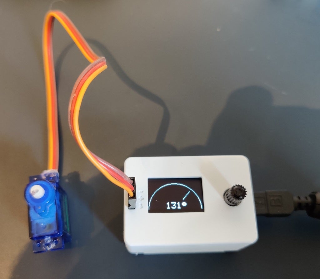
<p>Purpose:<br/> I wanted to build a compact device for testing and setting the position for RC servos. This device is pretty simple and cheap to make. If you use the generic version of these components you should be able to build this for < $10.</p> <p>I particularly like how the analog "speedometer" dial turned out for showing the servo position.</p> <p> <figure class="media"> <oembed url="https://youtu.be/QxGPE6oh-ow"></oembed> </figure> </p> <p>Materials:<br/> -Arduino Nano<br/> -Adafruit SSD1306 0.96" OLED display (or generic version)<br/> -10k potentiometer<br/> -male header pins x3<br/> -M3 screws<br/> -wires (I used 22 gauge braided with silicone insulation, easy to bend into position, even smaller might be better)</p> <p>Special Tools needed:<br/> -M3 tap<br/> -soldering iron</p> <p>Printing Notes:<br/> -Both upper and lower case parts are in the same file.<br/> -If you use the .3mf file, in some slicers (Prusa slicer) both components are overlapping when added into your build area. Just do an auto-arrange and they'll separate.<br/> -Be sure to orient the case parts so the "top" and "bottom" of the case are on your build plate.<br/> -All three parts are designed to print without support.</p> <p>Instructions:<br/> -After printing the case and the clamp, you'll need to tap the various holes for the M3 screws. You may also need to clean out the pass-through holes on the case bottom and the holes for the header pins.<br/> -I soldered wires to all components except the Arduino Nano before I assembled the case.<br/> -The male header pins are used to create the connector for the RC servo. Press these into the top of the case, and press through only enough of the header pin into the case to provide something to solder the connector wires to. The soldering process should heat the pins enough to bond them in the case.<br/> -The Arduino pins to connect the wires to are commented in the code. Note- the potentiometer center tap is connected to the nano, the outside two are connected to +5v and ground.<br/> -The OLED screen is held in place by the case top on one side<br/> -The clamp holds the OLED screen and potentiometer in place<br/> -when you close the case be careful not to crush any of the wires<br/> -load the encluded sketch onto the Nano</p> <p>Solidworks 2020 files are included for your remixing fun.</p> <h3> Print Settings</h3> <p><strong>Printer Brand:</strong></p> <p>Prusa</p> <p><p class="detail-setting printer"><strong>Printer: </strong> <div><p>I3 MK3S</p></div><strong>Rafts:</strong></p> <p>No</p> <p><p class="detail-setting supports"><strong>Supports: </strong> <div><p>No</p></div><strong>Resolution:</strong></p> <p>0.2mm</p> <p><p class="detail-setting infill"><strong>Infill: </strong> <div><p>15%</p></div><br/> <strong>Filament:</strong><br/> Generic PLA White <br/> <p class="detail-setting notes"><strong>Notes: </strong> </p><div><p>Parts are all designed to print without support and without rafts.</p></div></p> </p></p></p> Category: Electronics
With this file you will be able to print RC Servo Tester with your 3D printer. Click on the button and save the file on your computer to work, edit or customize your design. You can also find more 3D designs for printers on RC Servo Tester.