Receptacle/Outlet control via Raspberry Pi
prusaprinters
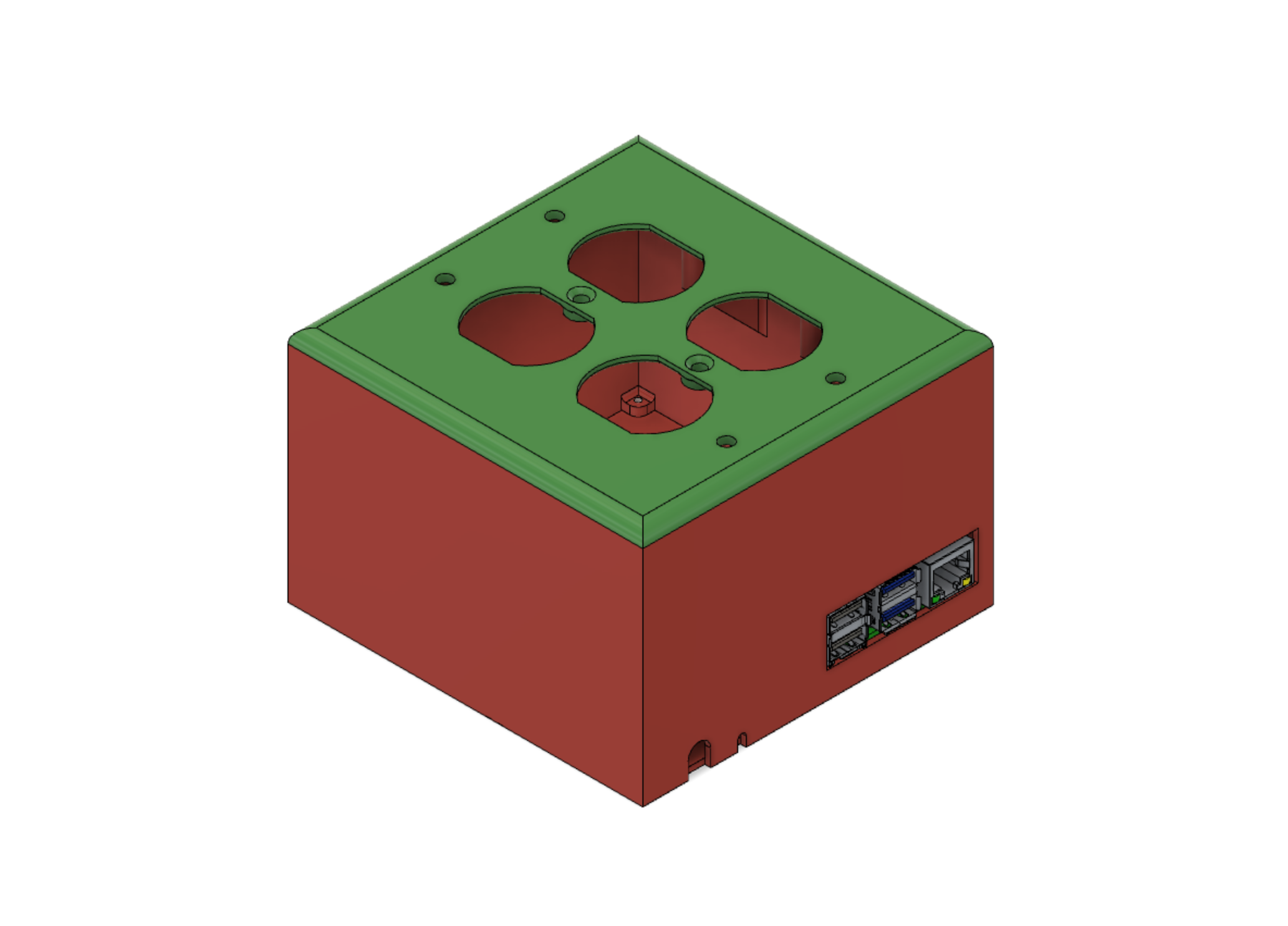
<p>Used for our Christmas tree (hence the coloring), in my deployment, this project runs Music Player Daemon (MPD) and has the audio jack extended out the side, for a set of desktop computer speakers, whose powered amp is controlled by one of these receptacles. These are purely optional, if one just wants a Pi controlled outlet strip.</p> <p>Requires:</p> <ul> <li>Raspberry Pi 4, but a 3 should fit (perhaps even a 2, still) </li> <li>4-port Relay board, w/ screw holes measuring 65.25mm x 45.25mm apart</li> </ul> <ul> <li>Aukey USB-C power block charger</li> <li>6" Male-to-Male USB-C connector</li> <li>3.5mm Male-to-Female audio jack</li> <li>(13) M2.5x4mm screws, for general assembly</li> <li>(4) 6-32 receptacle screws, for receptacles</li> <li>(2) 6-32 oval head screws, for outlet cover.</li> </ul> <p>Assembly<br/> As this project mixes both high and low voltages, I will not be providing a schematic, due to fire risk. Do not proceed with this project if you're not entirely comfortable dealing with high voltage. This project is a basic (8) GPIO manipulation, (4) for the LEDs and (4) for the relays, each of which is wired to interrupt the 'hot' wire of one receptacle. I won't add more detail than that.</p> <p>I've included (2) cover plates, a simpler "no LEDs" version and a design with LEDs (shown).</p> <p>Assembly is designed to be dropped in from the bottom, and the through holes for the Pi's ports require such. The relay board could be top-down or bottom-up.</p> <p>Other Notes:<br/> Note 1: Due to the offset caused by the Pi's location with respect to the screw holes and the molded stand-offs used to help support both the Pi and relay board, the bottom plate is not symmetrical. Therefore, two indexes have been placed on opposing sides to aid in locating the proper orientation.</p> <p>Note 2: With the thickness of the PCBs and locations of the mounting tabs, I designed the system to be assembled with almost any M2.5 screw length. That said, there is one under the Pi that may interfere with the pins. To be safe, make sure to use nothing longer than M2.5x4mm.</p>
With this file you will be able to print Receptacle/Outlet control via Raspberry Pi with your 3D printer. Click on the button and save the file on your computer to work, edit or customize your design. You can also find more 3D designs for printers on Receptacle/Outlet control via Raspberry Pi.