Regenerative Compressor (Ring Blower, Side Channel Blower) for CPAP Cooling, etc.
prusaprinters
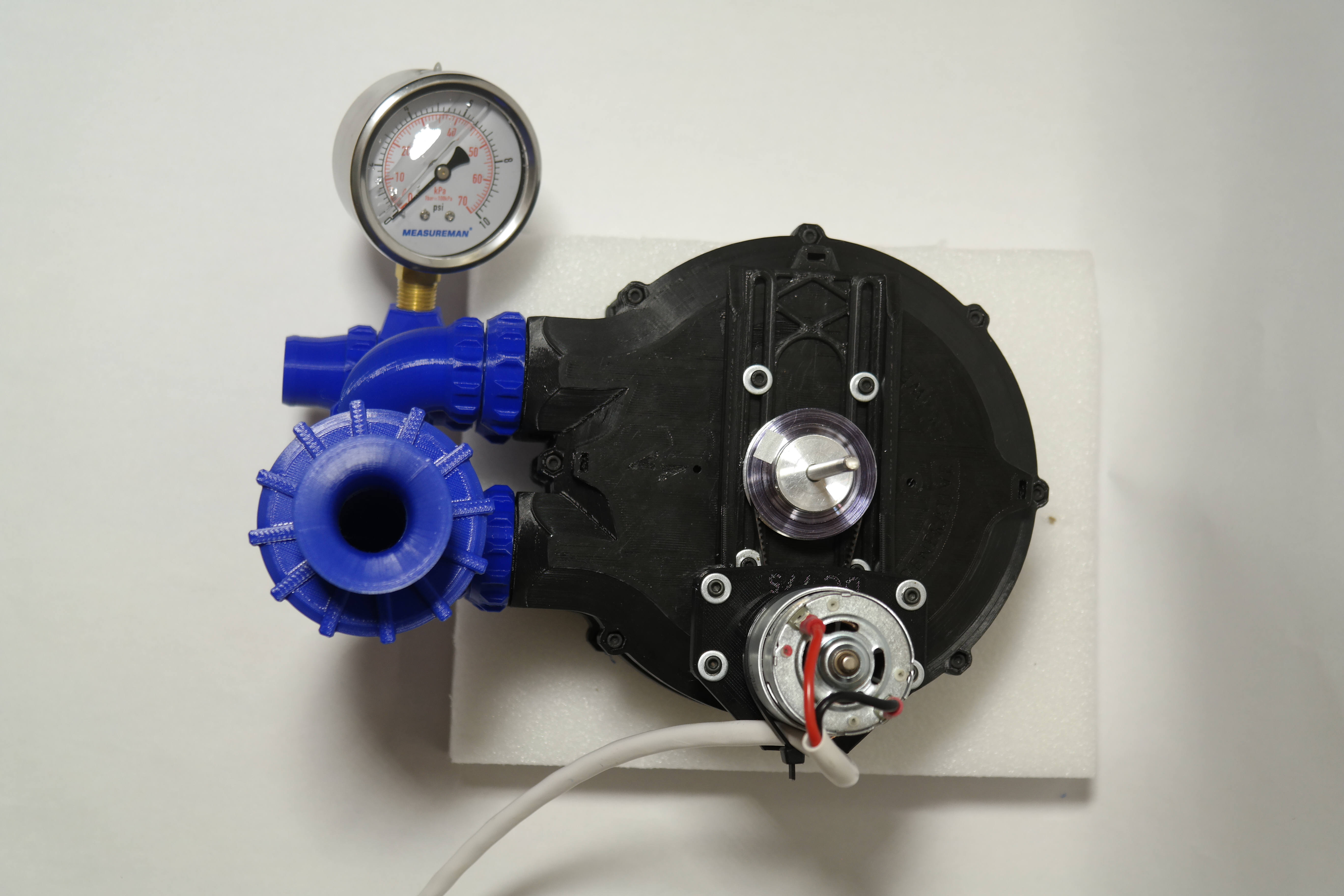
<p>Regenerative compressors provide good pressure head and medium flow at low RPMs. I designed this one from scratch in Sketchup to play with the concept for potential CPAP cooling on my printer. It starts to build pressure head at fairly low RPMs, but it needs plenty of power! A torquey low-RPM brushless motor, or possibly even a beefy stepper motor, would be ideal, but a DC 775 motor works very well for higher speeds and doesn't cost much. A 12V 1-amp motor with a belt reduction to spin the impeller around 5-600 RPM is about as low as this will go for providing useful flow. A 12V 10A (peak) motor should be good for 1+ PSI of pressure head and 10+ CFM, depending on the RPMs and belt reduction. To date, I have measured maximums of 1.25 PSI (output throttled) and 11 CFM (output open) with a two-stage build at about 4300 RPM. As a bonus, it is fairly resistant to damage from inhaled debris, not that I recommend chucking stuff in it (or using it as a vacuum cleaner).</p><p>You can build one unit for a single-stage compressor, or you can stack multiple units on a common shaft for a multi-stage compressor that builds more boost. Check out this performance review! </p><figure class="media"><oembed url="https://youtu.be/ObnN-f2A6mc"></oembed></figure><p>IMPORTANT: this is a prototype and you must DIY your motor solution. I do not have a standardized or “best” recommendation yet, but a 10-Amp DC 775 that does 6k at 12V works quite well, and can be had on Amazon for US $20 or less! You need something that will be happy and powerful in the 2k-6k+ RPM range, so this is not a job for a super high-RPM motor unless you use a belt reduction. The above-mentioned 775 motor specs run this compressor easily at 3:1 reduction (very little throttling versus load) for lower-pressure/CFM needs, or can run it at 1:1 and get about double the RPM, where it struggles more with loads and heats up but still pushes a lot of air. (Also, be warned that it SCREAMS over about 3K RPM without the silencer. I TAKE NO RESPONSIBILITY FOR YOUR HEARING. USE PPE!) A two-stage build can be driven nicely on 1.5:1 to 2:1 geardown with the same motor.</p><p>If you don't want to use a 550 or 775, but would rather go brushless, I would recommend creating your own motor mount for this. The casing has a mounting pattern of 6 M3x8mm deep holes on a 35mm radius. There are motor mounts provided for 775 (29mm M4 mounting screw spacing) and for 550-size DC motors (25mm M3 mounting screw spacing). Otherwise you can use the sliding mount and create your own motor mount (the M3 hole spacing is 24mm x 62mm).</p><p>Possibly the best power solution would be a heavy-duty stepper motor, like a NEMA 23, as one of the strengths of this design is its ability to perform across a wide range of input RPMs, but PWM-driven motors struggle to run quietly at the low end. However, I haven't tested this, and you would need to devise your own motor mount and control solution.</p><p>Printing tips:</p><p>READ THE STL DESCRIPTIONS!!!</p><p>Slice the impeller with “union overlapping volumes" because I couldn't be bothered to solid all those blades (sorry). I used 3 perimeters and 10-15% infill with fine results in PLA. For the housings, you only need support for the nozzle threads, so try to block it off from anywhere else. Otherwise, only the nozzles and accessory pipes need supports. You will need to embed 6 M3 nuts in each housing for the motor mounts; at .2 layer height, the best time to pause and insert will be around layer 22. A “nuts” warning will appear in the infill when it's about time to put them in!</p><p>There is a one-piece impeller included if you want to go the simple route, but it is NOT RECOMMENDED as it can't be easily tuned for flatness/centering. The multi-part impeller can be tuned for these. However, the prints require excellent print tolerances to fit together. Thankfully, you can iterate for a good fit with your printer by adjusting just one small part (the alignment ring) so you don't need to worry about having to throw away any big prints if they don't fit correctly on the first try.</p><p>For general assembly overview, especially for the multi-stage build, I strongly suggest watching the YouTube video.</p><p>MINIMUM prints and Hardware you will need for a single-stage build with the one-piece impeller and no silencer (but you do want the silencer):</p><ul><li>One-piece impeller</li><li>2-4x 0.9mm 5mm spacers (larger spacers are also included in the STLs)</li><li>Upper and Lower housings</li><li>Sliding motor mount</li><li>Upper motor mount to fit your motor</li><li>2x Nozzle lock collars</li><li>2x Nozzles sized for your hoses</li><li>12x M3 nuts to embed in the housings</li><li>2x 5x10x4x11.6F flanged bearings (MF105 - get good ones - I used ABEC 9)</li><li>1x 70mm+ 5mm shaft</li><li>2x 5mm lock collars with 10mm OD and 2x+ 12mm M4 set screws for them</li><li>8x 12mm M3 screws and nuts to fasten the housing together</li><li>4x 12mm M3 screws and washers to attach the sliding motor mount, if using</li><li>4x 20mm M3 screws, washers, and nuts for the motor mount</li><li>2x 8mm M3 (for 550) or M4 (for 775) screws and washers to attach a DC motor</li><li>Your choice of motor, pulleys, and belts (A 775 motor is simple because it has a 5mm shaft and can use easy-to-source GT2 printer pulleys; I recommend getting a range of pulleys, like 60T, 40T, and 20T, so you can experiment with drive ratios and find one that won't burn up your motor)</li><li>Adhesive window sealing foam tape (trim to size)</li></ul><p>RECOMMENDED intake silencer:</p><ul><li>OMIT the intake nozzle.</li><li>Instead, print:</li><li>1x “straight” accessory thread adapter</li><li>1x accessory elbow</li><li>Silencer housing</li><li>Silencer lid</li><li>Intake Stack</li><li>OPTIONAL: print the silencer sleeve and the silencer sleeve retainer ring set. Watch the YouTube video to see how these are assembled. The sleeve prints flat, and you must roll it up (warm it up if needed), superglue it into a tube shape, and then superglue the ends to the retaining rings. Wrap in fabric or foam, then install in the housing.</li><li>ALTERNATELY: the silencer works almost as well if you just roll a kitchen sponge into a ring and stuff that in the housing instead – just make sure the center is nice and clear.</li></ul><p>RECOMMENDED multi-part impeller print setup and hardware adds:</p><ul><li>OMIT the one-piece impeller.</li><li>Instead, print the hub core, alignment ring, spoke wheel, and impeller ring, along with the spacer set. Print the spacers at 0.1 layer height. Printing these parts with outer perimeter printed FIRST is HIGHLY RECOMMENDED for the best dimensional accuracy. (This is the business end of the whole contraption and any issues with fit/finish/strength will come back to haunt you, so this is the time to slice for high quality, not super speed!) </li><li>3x 12mm M3 screws and nuts for attaching the multipart impeller spokes to the impeller ring.</li><li>2x 8mm M4 grub screws to balance the longer set screws that actually screw into the lock collars (insert them into the holes opposite)</li><li>2-4x 8-12mm M3 grub screws to balance the overall assembly (screw into the periphery).</li><li>The required tolerances for this version are tight. If the core, alignment ring, and spokes jam or slide together too easily, try changing your slice settings for the alignment ring to expand or contract it slightly. When the fit is correct, the parts should slide together without too much trouble, have enough friction to stay together reliably on their own, and yet not get stuck together either. You MUST be able to easily disassemble it without wrecking it with tools, since the hub locking screws can only be accessed with the rest of the assembly off.</li><li>For tuning flatness, the “default” configuration is to use 1x of the largest (2mm) spacer size between each spoke and the impeller ring. The spacers are 2mm, 1mm, 0.5mm, and 0.2mm. If the impeller does not spin flat, find the highest point and start by adding one of the thinnest spacers on the closest spoke OR reduce the spacer stacks on the opposite side. (NOTE that this is counterintuitive: adding spacers pushes the ring DOWN.) For the two I've built, I was able to get near-perfect flatness with just 1-2 of the thinnest spacers.</li><li>For tuning centered-ness, the default configuration (centered) is with the 3 markers aligned on the core, ring, and spokes. The bore can be moved up to 0.6mm off-center by rotating the ring relative to the hub core marker, and you can rotate the location of the bore by rotating the spokes relative to the ring. I did not need to adjust this, but if your lock collars are bad, you might need to.</li></ul><p>Multi-stage bonus hardware and prints:</p><ul><li>For each extra stage, print the “MULTISTAGE ONLY” top housing instead of the normal top housing. This has NO embedded nuts, but instead has through-holes so you can attach units together. The through-holes have a thin skin at the bottom that you must drill out, along with the drive shaft entry.</li><li>You must also print some of the “accessory” parts to connect the stages together. See the YouTube video for assembly hints; the idea is that the accessory thread adapters replace the nozzles so that you can use the accessory pipes instead. 2x Lock Collars, 2x 30-degree accessory adapters, 2x elbows, and the F-F connector pair should work nicely to connect one stage outlet to the next stage inlet. For sealing the pipes together, I used rings of closed-cell packing foam, but you could also use glue, caulk, or even rubber bands.</li><li>6x 12mm M3 screws to attach the extra stage “MULTISTAGE ONLY” top housing variant to the bottom housing of the first stage.</li><li>More window sealing foam tape to create two sealing rings between the stage housings (see picture). It is CRITICAL to apply tension to the housing connection screws EVENLY and in small amounts (just like when putting a wheel on a car) so that this sealing foam compresses evenly and the housings end up flat compared to each other (otherwise, hello shaft misalignment).</li><li>1x 150mm+ (for two stages) 5mm shaft. (200+ should be okay for 3, but not tested).</li></ul><p>Construction tips:</p><p>Make sure the impeller spins flat. For the one-piece impeller, You may need to trim the shaft hole and/or play with set screws to get it nice and aligned. There are peripheral pockets in the impeller to place M3 grub screws for balancing, but I didn't end up needing them. You may need to sand the interior air dams/rub lines to get friction-free spinning with the housing screwed shut. Use the provided spacers, stacked if needed, to get the clearance right. If assembled properly, you should be able to turn the housing and watch the drive shaft counter-spin as the impeller stays still inside. You will also need to drill or cut out a hole for the shaft on the housing side where you plan to mount the motor. Leave the other one capped off to avoid pressure loss! Finally, be sure to orient the impeller so the cupped blade surfaces are spinning away from the inlet. If you run it backwards, the performance will be worse.</p>
With this file you will be able to print Regenerative Compressor (Ring Blower, Side Channel Blower) for CPAP Cooling, etc. with your 3D printer. Click on the button and save the file on your computer to work, edit or customize your design. You can also find more 3D designs for printers on Regenerative Compressor (Ring Blower, Side Channel Blower) for CPAP Cooling, etc..