Remote Controlled Arduino Car
thingiverse
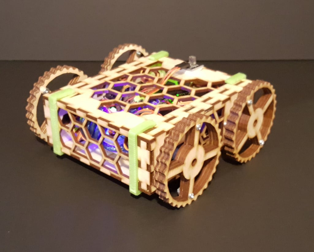
Remote Controlled Arduino Car by Kevin Mercer www.KevinRMercer.com Overview This Arduino car utilizes four continuous rotation servo motors for quick, accurate movements and a tight turning radius. An infrared remote and receiver allow wireless operation. The car is designed to be laser cut from 1/8 inch plywood or acrylic sheet. Its components are connected with finger joints, requiring no glue; instead, the chassis is held together with four 3D printed clips. Twelve machine screws and nuts are also required. Materials 1 x Arduino/Genuino Uno Development Board 4 x Continuous Rotation Servo Motors (With Horns and Screws) 1 x Mini Breadboard 12 x 4-40 Machine Screws & Nuts, 1/2 inch each* 2 x 12 inch x 24 inch x 1/8 inch Plywood or Acrylic Sheet 1 x Rechargeable Power Bank 1 x Infrared Receiver & Infrared Remote 25 x Jumper Wires 2 x LED's (Optional) 4 x Rubber Bands (Optional) Several Small Zip Ties Command Strips or Adhesive-Backed Velcro Links Development Board https://www.amazon.com/SainSmart-Arduino-ATmega328P-Development-Board/dp/B00E5WJSHK/ref=sr_1_5?s=wireless&ie=UTF8&qid=1515902048&sr=1-5&keywords=arduino+uno Motors https://www.amazon.com/FEETECH-FS90R-Pack-Continuous-himalayanelixir/dp/B074BFQC3Q/ref=sr_1_cc_2?s=aps&ie=UTF8&qid=1515902076&sr=1-2-catcorr&keywords=continuous+rotation+servo Power Bank https://www.amazon.com/Aibocn-External-Battery-Charger-Flashlight/dp/B013HIR1Q2/ref=sr_1_1_sspa?ie=UTF8&qid=1515901925&sr=8-1-spons&keywords=power+bank&psc=1 Infrared Remote & Receiver https://www.bananarobotics.com/shop/IR-Remote-Control-Kit?gclid=EAIaIQobChMI3P6R0cWU2wIVlTbACh2QsAMKEAEYASAAEgL9zPD_BwE Tips Sand the servo-shaped holes with an emory board before installing the motors. Fit is tight, but forcing a motor into place may crack the plywood or acrylic. Each servo fits in its hole only one way; note the small notch cut for the servo's three wires. Only one screw is required per motor. Enlarge the hole on each servo's ''wing'' to 1/8 inch large after fitting. The provided .STL of the full-width wheel is available for download if you prefer to 3D print it instead. Pre-drill holes for the servo horns in a 3D printed wheel; use two 1/2 inch 4-40 machine screws per wheel. Any cross-shaped or circular servo horn will work; each wheel requires only two servo screws for attachment. Add a rubber band to each wheel if your car seems to get too little traction on slick floors. A 3 inch by 1/4 inch band will work well. If your infrared receiver does not receive signals from odd angles, add a second receiver and split the circuit in the same fashion as either the lefthand or righthand servos. Continuous rotation servos may require ''zeroing''. Adjust the small Phillips screw on its bottom side until the motor stops rotating if it rotates when it should not. Your infrared receiver shows three lettered pins: ''G'', ''R'', and ''Y''. ''G'' = Ground, ''R'' = 3.3v, and ''Y'' = Signal. The provided .INO prints your infrared remote's hexadecimal codes in the serial monitor, so you can identify each button's corresponding HEX code. Use this to establish which buttons will drive the car and in what directions. https://youtu.be/uCo3nz9ylbg
With this file you will be able to print Remote Controlled Arduino Car with your 3D printer. Click on the button and save the file on your computer to work, edit or customize your design. You can also find more 3D designs for printers on Remote Controlled Arduino Car.