Remote for Steerable Robot Drone
thingiverse
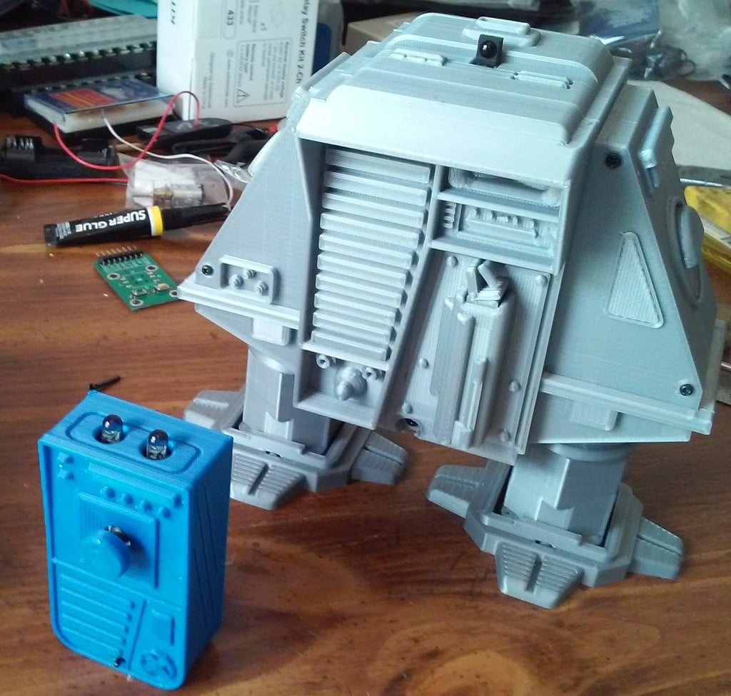
This is a custom remote for my Rocking Body Walking Robot Drone #5 steerable version, which I previously posted on Thingiverse: https://www.thingiverse.com/thing:3102186 The remote wasn't strictly necessary, but it matches the robot's aesthetic better than a universal TV remote. It uses an Attiny85 programmed with the Arduino IDE. The input comes from a digital thumbstick sold on Ebay as "Navigation Button Module 5D Rocker Joystick Independent Keyboard for Arduino MCU." The thumbstick needs to be de-soldered from its board so it can be used in this project. It has left, right, up, and down functions, along with a button that's triggered when the stick is pressed. This button isn't utilized in this project. The power supply consists of two 2032 cells wired in parallel to produce 3 volts. I chose this setup because 6 volts might be too high for the Attiny, and it also allows more current for the LEDs. I modified a serial battery box from Banggood into a parallel configuration: https://www.banggood.com/CR2032-Button-Battery-Holder-Case-With-OnOff-Switch-p-970429.html?rmmds=search&cur_warehouse=CN Modifying the case involved drilling a hole and soldering a couple of wires. The included images show where to solder the wires and how to orient the batteries in the case. There's no polarity protection, so ensure you get the batteries in correctly. Check the polarity and voltage with a meter just to be sure. The switch was removed from the battery box and mounted inside the remote case. The case and switch are simply hot-glued into place. I created my pc boards using a small CNC engraver, but they can also be built on perf board. The thumbstick is a surface-mount part, so it's mounted on the solder side of the pcb. It has a couple of small locating nubs on its backside that need to be trimmed off so it will lay flat. I used flush-cut wire cutters for this task, but an exacto knife would also work. The other components are mounted on the opposite side of the board. The 3D print files include a template for positioning the thumbstick and cutting out the board, ensuring that the stick lines up with the hole in the remote case. The required materials include: * One Attiny85 * One navigation button * Four 2MM screws (approximately 5MM long) * A serial battery box (modified to parallel configuration) The code for this project is based on some code from Dave Jones EEVBLOG. It uses delay functions and doesn't require any libraries. To make it work, you need to set your fuses for an 8 MHz clock. If the program doesn't function as expected, the Attiny's clock may need to be calibrated. I've included a new program for the Arduino Pro Mini in the robot, which is still compatible with a Sony remote like the original program. The Eagle board and schematic files are also included. The 3D printed parts consist of the top and bottom cases and a faceplate that's glued onto the top case. There's also a small button that's glued to the button included with the thumbstick. The bottom case includes extrusions that will hold the pc board snugly against the top case. The case is held together with 2MM screws, and the battery box is hot-glued to the bottom of the case. Avoid using too much glue in case you need to disassemble the remote to replace batteries. I'm pleased with how it turned out, and it matches the robot's appearance well. The range is at least 10 feet (3 meters). I think one without the button function would have a better feel. Building the remote isn't as difficult as building the robot but still involves soldering and programming the chip. Good luck, Rick
With this file you will be able to print Remote for Steerable Robot Drone with your 3D printer. Click on the button and save the file on your computer to work, edit or customize your design. You can also find more 3D designs for printers on Remote for Steerable Robot Drone.