Renoir's RepRap Arduino Mega Shield
thingiverse
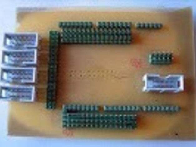
A RepRap Arduino Mega shield has been designed by me for use in transitioning between generations of electronics. Key features include single-sided PCB design for ease of homemade boards, five stepper driver headers that match existing gen3 electronics, a UI interface header that should align with gen4 electronics, and a 10-pin IDC heater connector to plug in MOSFET driver board. The shield also includes an I2c header as per standard boards, and optional extra 3-pin headers for digital in/out and analog in, allowing for easy addition of temperature sensors, kill switches, extra limit switches, etc. However, note that the +5v/Gnd/Signal headers for digital and analog pins are directly connected to the internal arduino 5V supply; hence, do not use these headers to run major circuits. Instead, utilize a separate power supply. My build process involved tinning copper pads, converting standard header pins to through-pins, aligning pins, and soldering. A suggestion is to apply the silkscreen layer before soldering to avoid writing pin numbers with a sharpie. Eagle files for the Arduino Mega shield, pins only, are available for download on my site. The design has been updated with thicker traces, ground plane, and 0.3mm center drills for easier home-etching.
With this file you will be able to print Renoir's RepRap Arduino Mega Shield with your 3D printer. Click on the button and save the file on your computer to work, edit or customize your design. You can also find more 3D designs for printers on Renoir's RepRap Arduino Mega Shield.