Replicator MightyBoard Protection Part 2:  ESD Shielding

Replicator MightyBoard Protection Part 2: ESD Shielding

thingiverse

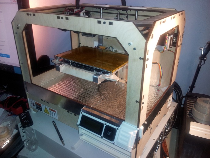
From Part 1, we know that Replicator MightyBoards occasionally blow up. One of the suspected causes of those blow-ups is Electro-Static Discharge (ESD). Part 1 offered some protection from ESD on the EndStop data lines, and in this Thing, we'll try to improve on that to offer some protection to the Replicator in general. The most common source of ESD damage is from the human body, discharging an accumulated charge into a sensitive electronic circuit. You accumulate a charge via motion or friction with an object. You discharge when touching a conductive object; i.e., that spark when you touch a doorknob. One of the insidious things about ESD damage in electronics is that it is cumulative. You might zap your Replicator, and it keeps on working, so you think you've dodged a bullet. But the damage may still be there, waiting to accumulate further damage with the next zap, or just planning to spontaneously distruct at some random time in the future. And here's another secret: ESD discharges that you may not even feel, may still damage your Replicator. There are sort of three general ways to protect against ESD in a system: Isolation; by preventing any path for ESD to reach sensitive circuitry. Shunting; by providing an alternate path to ground for an ESD event by adding a device to the sensitive circuits. Interception; by discharging the ESD source before it comes in contact with sensitive circuits. ... and I should also mention ESD prevention, see the beginning of the Instructions below. Isolation is pretty much impossible in the Replicator. While you may think the wooden case would make this easier, the fact is that there are many sensitive circuits that are exposed throughout the box, that are easy for a user to come in contact with. Shunting was done with ESD diodes for the EndStop signal lines in Part 1, and more will be added to the LCD cable in an upcoming Thing. However, it's just not practically possible to get an ESD device onto every exposed line in the Replicator. (Note that the MightyBoard revision used in the Rep2 and 2X has ESD devices added to every line.) That leaves interception, which this Thing is going to work on. It may or may not be attractive, depending upon your POV, but I think it will be a considerable help in keeping your Replicator safe from ESD damage. So, we're going to wrap a strip of conductive aluminum tape completely around your Replicator, and ground it. Plus ground the aluminum build plate (if you still use it) and the aluminum platform arms (if you have them). The idea being, that you will be likely to touch one of these items before you touch something sensitive in the Replicator. And, if you remember to consciously discharge yourself at one of these grounded points, even better. Note that you may implement this Thing without having installed the EndStopESD board from Part 1. Note also that installation of this Thing is strongly recommended before installation of the LCD ESD add-on board that will be presented in Part 3. Instructions It's always a good idea to practice good ESD (Electro-Static Discharge) prevention around your Replicator at all times, regardless of any 'protection' you may have added: ESD Prevention Avoid wearing clothing that generates static electricity. Avoid placing your Replicator in a carpeted area. When approaching your Replicator, touch something grounded before you touch the Replicator. Be aware that low humidity conditions can increase ESD problems by a factor of 10X. Also be aware that unpeeling just about any kind of tape generates an enormous static charge. It wouldn't be a bad idea to wear an anti-static wrist band when working on your Replicator. (Note that so-called “wireless” or “cordless” anti-static wrist bands are a hoax, and are less than worthless for preventing ESD damage.) To be effective, the wrist band must be grounded. Prelude: In addition to this Thing, you must print and install either the Replicator Keyboard Cover or the Replicator Front Panel. Both of these Things cover the ridiculously exposed LCD board, and serve to provide isolation there from ESD. Note though, that the Keyboard Cover will not fit on the upcoming LCD ESD Thing that will be posted in [Part 3]( http://www.thingiverse.com/thing:91656) of these Things. Unless someone steps up to design a cover that fits the LCD board with the LCD ESD Thing, the simplest choice is print and install the Front Panel Thing. Materials: Aluminum duct tape, 2-inches wide, about 10 feet. (Note that this is 'real' duct tape, not the grey stuff - nobody in their right mind would actually put that on their ductwork.) It's available at any hardware store or Wal-mart; here's the stuff at Amazon. Ribbon cable. 4-to-6 conductors; you'll need about 30 inches. Crimp lugs. I prefer to use ring lugs in the MightyBoard compartment, so that they won't be flopping around if the nut loosens. Spade lugs can be used elsewhere. M3 (or M4) screws and nuts, washers. Tools: X-acto knife and/or scissors. Allen wrench to access the MightyBoard area. Wire strippers/cutters. Drill and bit appropriate for a 3mm (or 4mm) screw. Crimp tool. If you didn't install the connection to the top of the power connector in Part 1, you need a large soldering iron or gun, sufficient to make that connection. Ohmmeter, DVM, DMM, or whatever you have to measure continuity. Skills: You will need to be able to solder a ground wire to the top of the power connector. Make crimp connections. Apply the aluminum tape. Printing: Nothing to see here, move along. Installation: Note: If you installed Part 1 then items below labeled [Part 1] have already been done and may be skipped. Remove the power and USB cables and orient your Replicator on end. Remove the bottom plate to expose the MightyBoard. If you haven't done so already, this is a good time to install the Replicator Power Cord Support Bracket by DDStarkey. This will prevent damage to the MightyBoard connector, and will absolutely prevent incorrect insertion. [Part 1] Drill a hole in the Replicator back panel for a ground screw. Right about through the 'n' in Brooklyn is a good spot. Be careful to not damage any wires inside. Drill a second hole in the Replicator back panel for another ground screw. This is spaced vertically above the previous hole, by about 2 inches, such that the hole enters the build chamber of the Replicator. [Part 1] Prepare a 2.5 inch piece of 4-8 conductor ribbon cable. On each end, individually strip the ribbon cable wires and twist the wires together. On one end, crimp a ring lug. Do not presolder the wires in the crimp. If it's a good crimp you don't have to solder at all; but you can afterwards if you must. [Part 1] Solder the other end of the cable to the top of power connector shell. This will require time and the heat of a large soldering iron or gun. Don't leave any loose strands of wire unsoldered. Unclip the extruder wiring tube from clamp on the outside back panel. Dismount the LCD board from the front panel of the Replicator. Unplug it from the cable and set it aside. If you have the board in a Front Panel Thing, dismount that too. Now we're going to wrap the Replicator with a continuous strip of the aluminum tape. It needs to be one strip without breaks, so it you mess up, it's best to just start over - the tape is cheap. Be careful - the tape edge can be very sharp. Starting in the middle of the Replicator side where the SD card slot is, remove the backing from about 18 inches of the tape and place it so that the upper edge of the tape is aligned with the lower edge of the build chamber opening, and so that about 8 inches of the end will wrap around to the back side. Burnish the tape flat as you go with a hard smooth object. Continue wrapping the end towards the back side. When you get to a corner screw, remove it, carefully keeping the nut in place. Place the tape and poke an 'x' at the hole with the tip of an X-acto knife. Replace the screw. When going around an inside corner, be careful pushing the tape into the corner - it is easy to tear. Finish placing the end of the tape on the back side. You can judge its position by keeping it a fixed distance above the interlocking tabs of the case. The end must extend far enough to cover the upper hole that was drilled in the case earlier. Poke an opening in that hole. Continue wrapping the tape towards the front, unscrewing, poking, burnishing as you go, keeping the tape aligned to the bottom opening of the build chamber. For the moment, tape right across the LCD, SD, and button openings. Continue around the front, side and back. Trim the end of the tape so that it will finish over the 'B' in Brooklyn but don't lay it down yet. Fold the end of the tape under, sticking it to itself, such that the folded area will fall over the hole that was drilled. The fold is necessary so that the aluminum surfaces will be in contact, making an electrical connection. Poke an 'x' over the hole. If you're like me, and I know I am, strip all of the tape off and start over, 'cause you weren't satisfied with the first effort. If you have already done Part 1, and have a screw installed in the lower hole, remove it now. Cut a strip of tape about 3 inches long and one inch wide. Remove the backing and fold over about 1/2 inch on each end. Place this strip so that it spans the two new holes on the back side, such that the folded areas are over the holes. Poke both of the holes open. Place a screw with washer in the lower hole and a nut on the inside and tighten. Place the ring lug from the cable from the power connector over the screw, [and the cable from the EndStopESD board if you've done Part 1], add a jam nut and tighten. Place a screw and washer in the upper hole, add a nut and tighten loosely. The washers are necessary so that the head of the screws don't tear the tape. We didn't care about the case screws, because those connections weren't electrical. You now should have a continuous band of tape around the Replicator, electrically joined at the ends by the fold and screw, and electrically joined to the lower screw by the short strip of tape, and ultimately joined to the power connector ground by the inside ground cable. Rinse and repeat as necessary. We're just gettin' warmed up. Perform the following steps marked [BWA] only if you have Bottleworks aluminum arms installed. [BWA] Cut an 8 inch length of ribbon cable. Strip the ends and twist the individual wires together; do not solder. Crimp a spade lug on one end. [BWA] Cut a 14 inch length of ribbon cable. Prepare the ends and crimp a spade lug on one end. Take the unfinished ends of both cables, insert them into a single spade lug, and crimp. [BWA] There are two screws on each side of the aluminum arms that attach the platform to the arms. Loosen (do not remove) the rearward screws on each side. Place the cable spade lug [8 inch end] under the left arm screw and tighten. Route the cable over the arms and behind the build plate, and place the middle spade lug under the screw on the other side [do not tighten]. Place the lug on the other end of the cable under the nut on the screw that you added from the tape wrap, and tighten. A strip of the aluminum tape is good for holding the cable flat on the top of the platform. [BWA] If you are not using your aluminum build platform, skip this step. Prepare a 2.5 inch ribbon cable with spade lugs on each end. Place one end under the right side platform/arm screw and tighten. Connect the other end to the right rear heater board/build platform screw. If you have an aluminum build plate and no BWA, prepare a 14 inch cable with spade lugs on both ends. Connect one end to the right rear heater board/build platform screw. Place the lug on the other end of the cable under the nut on the screw that you added from the tape wrap, and tighten. Do not run this cable in parallel with the HBP electrical cable. If you do not have a Front Panel Thing, trim the tape around the LCD and button openings. It would be best if the tape did not touch the LCD bezel. Remount the LCD board. Also trim the opening around the SD card slot. If you have a Front Panel, you only have to trim the tape in the button area enough to get the ribbon cable through. If you have the Front Panel, add strips of aluminum tape to the top of of the panel, above the LCD and button; fold it over the back edge. Likewise place a strip on the end around the SD card opening. See pictures. Replace the Front Panel. Unplug your power brick from the wall, and plug in the power cable from the brick to the Replicator. With your ohmmeter, measure from the ground prong on the AC plug, to various points on the tape you've just installed. Also measure to the build plate, aluminum arms and tape on the Front Panel, if you have any of those. All of those points should essentially be a direct short to the ground prong. Final Notes: There are all kinds of ways you could accomplish this differently, but here are a few points to remember: The flat tape is a very low impedance path to ground, better than a single wire. The ribbon cable's multiple conductors offer lower impedance than a single wire. Avoid routing any ESD ground cable parallel to any signal or power cables, or near the MightyBoard. Note also that there will be a [Part 3]( http://www.thingiverse.com/thing:91656) and 4.

Download Model from thingiverse

With this file you will be able to print Replicator MightyBoard Protection Part 2: ESD Shielding with your 3D printer. Click on the button and save the file on your computer to work, edit or customize your design. You can also find more 3D designs for printers on Replicator MightyBoard Protection Part 2: ESD Shielding.