Replicator MightyBoard Protection: Part 3 - LCD Board
thingiverse
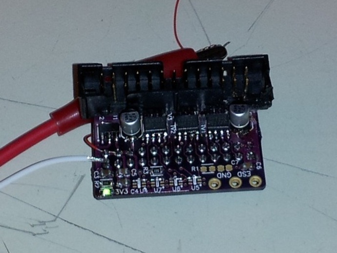
Fix issues with the LCD board on your Replicator MightyBoards by installing an LCD ESD board. Adds ESD protection diodes to all signal lines, a local 3.3V regulator, bulk and bypass capacitance for the 5V and 3.3V rails, proper level conversion of SD card signals, and adds termination components to improve Signal Integrity. To install, plug the LCD ribbon cable into the LCD ESD board, then plug the board into the LCD, being careful not to damage the ribbon cable or LCD board. If you have a Front Panel, cover the exposed boards with it instead of the Keyboard Cover. For an alternative installation, if you haven't installed the aluminum tape ESD shield described in Part 2, make a long piece of ribbon cable and connect it to the LCD ESD board and the ground screw from Part 1, ensuring it doesn't run parallel with the LCD ribbon cable. After installation, turn on your Replicator; the LCD display should come up normally and the green LED on the LCD ESD board should glow. Optional extras include adding a clamp-on ferrite filter around the ribbon cable for improved Signal Integrity and ensuring you have an anti-static wristband when working on your Replicator.
With this file you will be able to print Replicator MightyBoard Protection: Part 3 - LCD Board with your 3D printer. Click on the button and save the file on your computer to work, edit or customize your design. You can also find more 3D designs for printers on Replicator MightyBoard Protection: Part 3 - LCD Board.