Reprap - Funbot i1

Reprap - Funbot i1

thingiverse

Added 2016-05-13 ////////////////////////////////////////////////////////////////////////////////////////////////////////////////////////////////////////////////// If you ask in comments or message me be patient as i started a new nightshift work that makes me pretty tired. Only so you know..... Added 2016-03-23 ////////////////////////////////////////////////////////////////////////////////////////////////////////////////////////////////////////////////// I recommend for any new builders to use mad mikes lmu8 remix to avoid any problems with printed bushings. Its hard and tricky to get them working well with modern pla with all softeners added. Use cheap hard glossy pla for bushings if you can find it. Also recommended to use the Bowden remixes instead of the original mk8 version to make it simple. Cheers cliff mellangård. ////////////////////////////////////////////////////////////////////////////////////////////////////////////////////////////////////////////////// The longer spol top is to remove the pla from snapping of when you don't use the funbot and the extruder is homed. Something I noticed whas that the angle for the pla where to sharp so it snapped of after 1-2 days above the extruder. Its supposed to be placed in the rear. The project is more or less now finished and will only be cleaned up for now on. If you find any issues let me know so will I fix them. The y upgrade is up for the ones that want it and removes the nead for the m5 threaded rod,1 bearing and the coupler. The brand new mk8 combined print cooler and hotend cooler is also up that you see in my latest subscriber movie on my channel. Cheers. Update 7 is here now..https://youtu.be/JtbPYe5sG-w Added the brand new small spol roller wheels and you nead to print 4 of them. they are supposed to be like wheels on the pipes used for a spol holder so the filament roll rotates softly and should work just as fine on both eu 10 mm as us 3/8 pipes. They are to compensate for some rolls that have plastic rolls that seam to rotate with resistance towards the chromed pipes. also the brand new official funbot bushings that slides with very little resistance and flex on uneven surfaces. they have only bin tested so far on y and x axis with great results. no nead for multiple sizes anymore to fit all types of printers output. My inspiration for them is a mashup of igus and traditional lm10uu bearings where the long housing is for stability while the actual contact surface is minimal with good wear. All latest updates will be explained in a coming video on my channel so be patient ;) Only bad thing for me is that I seam to have to do a more updated build guide again soon ;) Added a new pulley wheel caps for the 2 624zz bearings on x and y axis that will make it a lot easier for the motors to work. also the new pulley wheel holder that works with the new caps for y axis. Small update with a new wider x carriage this will decrease the print size but increase stability and allowe wider bushing spacing. also have a hole to attach a m3 screw to adjust the endstop hit zone without adjusting the endstop it self. use a wide head m3 screw. Updated with 2 new files where one of them are a new taller z base t hat also have supports to work better on softer base plates. Also uploaded a new z carriage that have a small attachment so you can finetune the endstop with a m3 screw now instead of moving the endstop itself. I leaved the 2 old versions for the ones that want to use them instead. The new z base takes ages to print but is worth it ;) ( 6 hours on slow print on my prusa i3 ) The first beta release of the funbot firmware is now up. I still have a few things to do on it as the fans on the mk 8 behaves like a print cooler and speeds up at some stages during prints. this is now based on the latest release of marlin and they made so many changes compared to the old one I used so will take some time to go thru it all. But it works and iam using it now on my 2 funbots. Be carful and see that the fan is cooling your mk 8 as if not will it get clogged very fast. You can control the fan in slic3r with the fan settings this way so not bad at all actually :) This explains the drill guide for the base.https://www.youtube.com/watch?v=DQHVo17kaQA Keep in mind that build guide and boom are not up to date until I have uploaded everything and had the time to change it. The boom should be up to date now only some screw dimensions I might miss ?? Bowden recommended setup for funbot. You will only have to move the endstop for the y carriage.http://www.thingiverse.com/thing:547706 Sell this design??? I got the question from a reprap manufacturer if I mind if they produce and sell my design. The simple answer is that I don't mind but I would love if anyone share wath they do with my little design as its cool to see wath others do with it. I used my own money and skipped the suggested kickstarter solution as I want to share in a true reprap sense. When you print do it with 3 perimeters like I do to get it as accurate as possible to wath I do. I use a 0.4 nozzle so some people may nead to correct some settings in slicer to adjust to this. Also remember to not go above 0.3 in infill density when printing parts that will carry weight or be under force when printer is working. This is specially the z base and z base top part that holds a lot of weight. xxxxxxxxxxxxxxxxxxxxxxxxxxxxxxxxxxxxxxxxxxxxxxxxxxxxxxxxxxxx Work in progress created so I have a space to upload everything as soon as they are done. If you follow my bom and video build instructions so will you get this print area. New build guide in the works.(2015-01-15) Print size is x = 165 y = 170 z = 120 Hellboy print scaled up by 650%http://youtu.be/Bzg8LdMwHmQ Build guide part 1.( 2015 ) http://youtu.be/tJCb8C3XPSY Build guide part 2. http://youtu.be/Ju_Pu2KTsOE Build guide part 3. http://youtu.be/GOH9yER8a5I Build guide part 4. http://youtu.be/vI6VEQjI7E8 This is going to replace my old tinkerbot design. Keep in mind that the y base is redesigned from wath you see in the videos and picture to simplify assembly. This design uses cheap chromed copper pipes and printed lm10uu for rods and sliding bearings. Makes it very light and silent during prints. Have bin tested for a while that it actually prints well and are up to the task to be called a printer. Why I design my wacky builds? The goal of the printer like all my designs is a lightweight easy to ship and assemble, and the most important goal is that it must be extremely cheap to build and easy to get most parts nearby where you live. If we achive this so will we have soon have a repraper in every corner in the world independent on wealth and other things that can stop you :) 24-11-14 added various stl fixes and replacements because I noticed I uploaded the wrong files on some stl files.. Added a reprap logo as a alternative cable bracket. 25-11-14 Added a better bearing housing for the y carriage bearing on the drive shaft. Removed obsolete y carriage base. Be patient with the updates because there will be many and often during the initial prototyping stage of the printer. The first parts are more or less placeholders that work and have bin tested and many will be updated during time. 01-12-14 started on the wiki page.http://reprap.org/wiki/Funbot_i1 013-12-14 Uploaded the print cooler and large ramps cover. Latest upgrades are uploaded. Instructions Reprap Wiki ( Have also a much cleaner layout) (don't know why this gets messed up when you type it in here) http://reprap.org/wiki/Funbot_i1 Have started the work on updating the boom to its current state be patient :) Iam leaving the old at the bottom as a reminder if I mess something up :) And big thanks to mad mike and sisco for helping me with a complete boom :) Love you guys for doing it for me :) . . . . Base: 01 - 280mm x 240mm x 12mm MDF, Plywood, or Similar Bed: 02 - 210x190mm Acrylic or Aluminum Sheets 01 - 210x190mm Glas to print on. 02 - Paper clips to hold the glas in place Hardware: 09 - M3 x 8mm Bolt 02 - M3 x 10mm Bolt 04 - M3 x 14mm Bolt 03 - M3 x 16mm Bolt 09 - M3 x 20mm Bolt 04 - M3 x 25mm Bolt 07 - M3 x 30mm Bolt 09 - M3 x 50mm Bolt 01 - M4 x 18mm Bolt 01 - M4 x 50mm Bolt 01 - M8 Nut 10 - Zipties (Nylon Strips to Keep Wires Neat) 01 - 3M Double Sided Tape 02 - GT2 20 Tooth Timing Belt Pulley w/ Grub Screw 01 - 2000mm (2 Meters) GT2 Timing Belt ( For X and Y Axis ) Smooth Rods or Chromed Water Pipes: 02 - 270mm x 10mm or 3/8" Smooth Rod 02 - 320mm x 10mm or 3/8" Smooth Rod 03 - 290mm x 10mm or 3/8" Smooth Rod 02 - 100-160mm x 10mm or 3/8" Smooth Rod for Spool Threaded Rods: 01 - 210-220mm M8 Threaded Rod (For Z-axis) Bearings: 02 - 624ZZ Bearing (For Belt Pulleys) 01 - 608ZZ Bearing (For the top of the M8 Threaded Rod) Motors: 03 - NEMA17 Stepper Motors (1.7 Amps, 40mm Length) Extruder: 01 - Your Preference.. Mk8 Extruder Kit, Bowden, etc. Electronics: 01 - RAMPS 1.4 01 - Arduino Mega 2560 04 - A4988 Drivers 04 - Driver Heatsinks 03 - Endstop mechanical limit switch 01 - RepRapDiscount Full Graphic Smart Controller Power Supply: 01 - 12V 8+ AMP Switching Power Supply or Xbox Power Supply with Proper Voltage & Amps Notes: Specifics on the Hardware 50mm M4 Qty 1 50mm M4 screw x1 X idler bearing mounting. 18mm M4 Qty 1 18mm M4 screw x1 Y idler bearing mounting. 50mm M3 Qty 9 50mm M3 screws x5 z base / stepper mounting. 50mm M3 screws x2 Y Stepper mounting. 50mm M3 screws x2 X axis Stepper mounting. 30mm M3 Qty 7 30mm M3 screw x1 Y belt tensioner. 30mm M3 screws x2 LCD cover to base plate mounting. 30mm M3 screws x4 Y lower plate to Y upper plate mounting 25mm M3 Qty 4 25mm M3 screws x4 Y axis mounting. 20mm M3 Qty 9 20mm M3 screws x2 electronics bottom mounting. 20mm M3 screws x2 Y endstop base mounting. 20mm M3 screws x2 Fan mount to RAMPS cover. 20mm M3 screw x1 Z endstop plate mounting. 20mm M3 screws x2 X axis pipe attachment 16mm M3 Qty 3 16mm M3 screws x3 Z axis top pipe attachment. 14mm M3 Qty 4 14mm M3 screws x4 LCD to LCD cover mounting. 10mm M3 Qty 2 10mm M3 screws x2 Power Supply Mounting. 8mm M3 Qty 9 8mm M3 screws x2 Y endstop mounting. 8mm M3 screws x4 Y base plate to Y Carriage mounting. 8mm M3 screw x1 Y endstop plate to Y base plate. 8mm M3 screws x2 LCD cover hinge mount to RAMPS cover. . . . . . . . OLD - OLD - OLD - OLD . . . The 2 latest cable holders is something added to give a more professional and cleaner look. Boom will be added during a longer time so be patient. My fellow repraper Wayne Friedt have allowed me to include his case for the reprap full graphics controller i have modified to fit this bot. The cool thing with this case is that it also hides most of the cables and makes it look cleaner.https://www.facebook.com/my3dph?ref=bookmarks Boom so far. Wood for the base. I use a 12 mm thick mdf wooden board with the dimensions 280x240mm for the base. Bed material. The dimension of the 2 bed plates are 210x190 mm I use 3 mm thick acrylic plastic that you buy very easy at any home depot or carpenters store. I used 3 mm thick only because it where the dimension they had at my local store but if you find 4-6 mm thick at yours so would that be even better. This would give better stability to the bed area but is not neccesery as it works also with 3 mm,but this will bend slightly when adjusting levelling screws etc. But are rock solid during printing :) In the countrie where you live so could it be called something else but this is plain plastic sheets they sell to cover broken windows or as protection screen on cnc machines. I also got the attention from one builder that he found that my drill hole dimensions to attach the first acrylic sheet where wrong for him and found it to be better in reverse to wath I stated in the video part 7. 55 in on x axis and 60 on the y axis for the first hole. Be carefull!!!!! Keep in mind to drill up the holes for the 10mm pipes in reverse on your drill so will you not crack anything and get a better surface to slide in the pipes. M3 screws,nuts,washers z coupler uses 4 20mm long screws and the same amount of nuts. wood screws. coming soon! Pipes. ( Updated 2015-01-15) You will nead about 2.5-3 meters of chromed copper wather pipes with the outer dimension of 10mm. ( usa have other dimensions and 3/8" (9.5248mm) should work as good as European 10 mm.) If you build one in the us with these pipes let me know that everything works ok? If you experience a wobbly sensation with us pipes so simply scale down the bearing part to 98-99 in slicer as it should not affect the rest of it to much. With enough requests so will I try to do some official us parts to the 9.5 mm pipes for the printer. the main pieces should not be a problem as you always nead to drill them to insert the 10 mm pipes. y axis = 2 pipes 270 mm ( print size 170) x axis = 2 pipes 320 mm ( print size 165) z axis = 3 pipes 290 mm ( print size 110-120) Optional........ Spol holder = 2 pipes 100-160 mm ( This is more or less how you want it) (Iused 160 in my videos) summary.... 2 = 270mm long pipes. 2 = 320mm long pipes. 3 = 290mm long pipes. total = 2050 mm ( slightly above 2 meters) Threaded rods. 1 m5 threaded rod 100-110mm long for y carriage drive shaft. 1 m8 threaded rod 210-220 mm long for z axis. ( 210mm works for long motor shafts.) ( Keep in mind that many motors have various lengths on the shaft so to be sure should you probably add 10-20 mm to the z axis threaded rod to get the same print height that I state. ) 1 m8 threaded rod 150mm long for filament spol holder. Placeholders. the supplied endstop mount for the z axis is not mine and a placeholder as it is the prusa i3 reworks I simply cut to fit a 10mm pipe. Bearings. You nead 3 624zz skateboard bearings for the belt drive. 2 are used for the y belt and can be improved as it is 2 only to get a wider spacing. 1 is used for the x axis belt together with washer to keep the belt in place. If you wonder why I use these bearings so are they only 1 mm larger in diameter then a gt2 20 teeth pulley and fits nice on a m4 screw. you nead 1 625zz bearing for the y axis drive shaft. you nead 1 608zz for the filament spool spindle and have only bin tested on 1 kg spools. summary..... 3 = 624zz 1 = 625zz 1 = 608zz Motors. You nead 3 nema 17! 1 - 2 amp motors as the extruder I use comes with one already attached and is cheap. The motors in the video is 1.7 amp motors and are used because I had them at home. The dimension on the motors I use are 40mm but that should matter as long as you use motors close to that dimension, It is more critical to have a motor close to 40mm on the z axis as there is some very small ones that will conflict on the stability on the z axis if used there. The small ones should you be able to use on the 2 other places on the printer like x and y axis. Here did I buy my extruder. Very long delivery time 3-5 weeks from china. http://www.ebay.co.uk/itm/0-4mm-Nozzle-MK8-100K-Thermistor-Extruder-0-4mm-Nozzles-for-3D-Printer-Makerbot-/321362923154?pt=UK_CamerasPhoto_Printers_Printers_JN&hash=item4ad2b90e92 I recently found these on ebay and works just as good and are made in uk. 1-2 week delivery and improved nozzle and only slightly more expensiv. http://www.ebay.co.uk/itm/151552176556?_trksid=p2060778.m1438.l2649&ssPageName=STRK%3AMEBIDX%3AIT Power supply. http://www.ebay.co.uk/itm/310811933321?_trksid=p2060778.m2749.l2649&ssPageName=STRK%3AMEBIDX%3AIT Marlin Firmware. I will try to upload my prototype marlin code in a compressed file but its pretty straight forward and easy to setup. Her is some typical settings that neads to be changed...... configuration.h . #define INVERT_X_DIR true // for Mendel set to false, for Orca set to true .#define INVERT_Y_DIR false // for Mendel set to true, for Orca set to false // My mendel prusa wanted it like orca .#define INVERT_Z_DIR true // for Mendel set to false, for Orca set to true .#define INVERT_E0_DIR false // for direct drive extruder v9 set to true, for geared extruder set to false .#define INVERT_E1_DIR false // for direct drive extruder v9 set to true, for geared extruder set to false .#define INVERT_E2_DIR false // for direct drive extruder v9 set to true, for geared extruder set to false Use this in the beginning and then expand when you see that this is working ok. // Travel limits after homing .#define X_MAX_POS 145 .#define X_MIN_POS 0 .#define Y_MAX_POS 150 .#define Y_MIN_POS 0 .#define Z_MAX_POS 110 .#define Z_MIN_POS 0 This is stil temporary but is a start. .#define DEFAULT_AXIS_STEPS_PER_UNIT { 80 ,80 , 2560, 105.90192} .#define DEFAULT_MAX_FEEDRATE {450, 450, 2.5, 32} // (mm/sec) // X, Y, Z, E maximum start speed for accelerated moves. E default values are good for skeinforge 40+, for older versions raise them a lot. .#define DEFAULT_MAX_ACCELERATION {4500,4500,50,3200} .#define DEFAULT_ACCELERATION 1000 // X, Y, Z and E max acceleration in mm/s^2 for printing moves .#define DEFAULT_RETRACT_ACCELERATION 1000 // X, Y, Z and E max acceleration in mm/s^2 for r retracts // The speed change that does not require acceleration (i.e. the software might assume it can be done instanteneously) .#define DEFAULT_XYJERK 10.0 // (mm/sec) .#define DEFAULT_ZJERK 0.4 // (mm/sec) . #define DEFAULT_EJERK 5 // (mm/sec) Don't forget to remove // in front of the line that enables your type of lcd you use!!!!!! Slicer config. the slicer config neads to be loaded manually and then do you save each section in slicer if you don't want to do this manually everytime. I will also upload this soon. Some other peoples designs being used. Lm10uu replacement.http://www.youtube.com/playlist?list=PLlhi9-uGhiahbbcmVqSzW9BUu0Y_zJjHx Use this for a z coupler until i make one of my own.http://www.thingiverse.com/thing:19858

Download Model from thingiverse

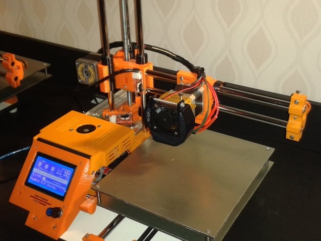
With this file you will be able to print Reprap - Funbot i1 with your 3D printer. Click on the button and save the file on your computer to work, edit or customize your design. You can also find more 3D designs for printers on Reprap - Funbot i1.