RepRap X2V3
thingiverse
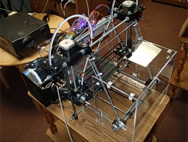
Rebranded and repackaged RepRap X2 with some additional hardware components, a new firmware, and a few software tweaks. The hardware changes include: * Metal parts (AKA vitamins) for X2 axis with longer horizontal sections. Below is the list of the changed rod lengths. Both, the original (RepRap X2 or Prusa's Mendel.g) and correspondent X2V3 rod lengths are listed. + Two threaded rods on top and one at the bottom of the machine that are used for mounting Z-motors, extruders and clamp the lower end of the vertical smooth rods: * Original - 440mm -> X2V3 - 465mm (extruder carriage) * Original - 440mm -> X2V3 - 465mm (Z-motor mount) + Two smooth rods the hotend carriages slide on: * Original - 392mm -> X2V3 - 410mm (extruder carriage) * Four threaded rods for connecting the frame triangles at the bottom front and back of the machine: * Original - 294mm -> X2V3 - 320mm (X stage) * Two smooth rods the motor fan mounts slide on: * Original - 392mm -> X2V3 - 410mm (motor stage) * A few of various nuts and bolts will be needed. For example, M3x8 screws and washers are used for mounting the motor fan mounts to the carriage. A few more of various nuts and bolts will be needed. For example, M3x8 screws and washers are used for mounting the motor fan mounts to the carriage. The additional parts of the machine that were modified and its changes are: * Frame triangles + Design files: frame.zip + Four legs and two top vertices are required to build the machine. + The rightmost is a bracket for connecting the plates. * X-ends + Design files: x-end.zip + Two copies of each part are required. The X-ends are positioned on the opposite sides of the X-stage. The rightmost is a motor driver for extruder 1 (dual head).
With this file you will be able to print RepRap X2V3 with your 3D printer. Click on the button and save the file on your computer to work, edit or customize your design. You can also find more 3D designs for printers on RepRap X2V3.