Respooler v0.1, Rewind your filament
prusaprinters
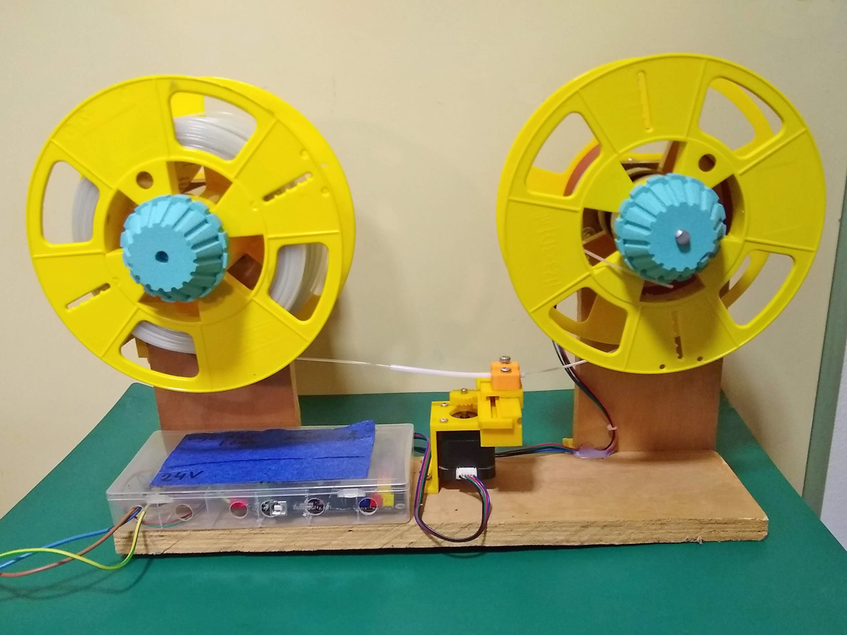
<figure class="media"><oembed url="https://youtu.be/NnuSktIjZZs"></oembed></figure><p><i>Double speed at :25</i></p><p><i><strong>Update 1 nov 2022</strong>: added a Python script for creating gcode for different spools. See the end of the description. </i></p><p>I got my hands for a few weeks or so on a new printer with an automatic filament switcher (AMS). Great piece of kit, but the AMS only accepts rolls of max 70mm width. Since I have/had a bunch of rolls wider then 70mm and rewinding with a drill was not a big success I tried to make an automatic rewinder. Which a few old printer-parts, some scrap wood, some hardware that I had in stock, a crappy box for the electronics and these printed parts it is a reasonable success and I had a lot of fun of making it. If you don't have fun in building and tinkering things like this or expect too much of it, please skip it.</p><p>The resulting spools are not perfect but sure good enough. The filament is already handled once before by spooling it on the original roll. Especially for bad coiled rolls the filament has already bends from that in it. The machine is not strong enough to unbend it (a good thing) and every bend is in the way of a perfect rewinding. But the result is good and often better then the original winding.</p><p>The model is build modular, so you can experiment with the placement of the different parts. Or integrate your own parts. It is a pretty archaic machine, so enough to tinker and update :)</p><p>You can create a simpler handcrancked version with the parts to begin with.</p><p>Is this machine too simple for you, take a look at the machine+ created by Warpster. </p><h5><strong>Frame:</strong></h5><p>I made the frame of a piece of scrap wood. You need three pieces, 1 piece of ca. 45 x 12 cm and 2 pieces of 22.5 x 12 cm. I used 11 cm width because that was laying around, a cm more is better. </p><h5><strong>The Motorbox:</strong></h5><figure class="image"><img src="https://media.printables.com/media/prints/281332/rich_content/5750b774-c496-4352-ad03-bbeb136190cd/motorbox.jpg#%7B%22uuid%22%3A%229f81bf7c-c372-41cb-b0fc-816f567b8017%22%2C%22w%22%3A1200%2C%22h%22%3A900%7D"></figure><p>Parts:</p><ul><li>Respool_motorbox1.stp/stl, 2 parts</li><li>respool_gears_24_48.stp/stl, 2 parts (D & E)</li><li>1 x nema17 steppermotor (A), the bigger the better</li><li>1 x Coupler 5-8mm (B)</li><li>3 x Bearings 22-8 mm (608ZZ)</li><li>M8 nuts (see description)</li><li>4x m3 bolts 20-22 mm for the nema 17</li><li>8x M4 x 30 mm bolts, m4 nuts and optional rings (or 4xM4 and 4 wood screws).</li><li>m3 bolts and nuts for connecting gears (see description)</li><li>1 x threaded rod M8 ca. 60mm</li><li>1 x threaded rod M8 ca. 200mm</li></ul><p>In the picture (D & E) you can see i drilled a hole through the axis (threaded rod) to fasten the gears. In that case you need 2 x 20-25mm M3 bolts and locking nuts. You can also use the holes in the gears for grub- screws (less secure, filing a flat spot on the rod will help).</p><p>The 4 M8-nuts (nuts and locking nuts) in the picture inside the box, well you can use them or not. If you drilled through the rod, and the placement of the gears has not to much play, you don't need them (I was to lazy to remove them). You can also use “nylon-insert lock nut” or Loctite. The Nut at F is secured by the nut in the spoolfastener. To be sure use a “nylon-insert lock nut” or an extra nut for locking or loctite. </p><p>If a double nut get loose it can lock itself against the wall or bearing, wich will end up in a crash. So be sure they are tight or don't use them.</p><p>The two axis must run freely.</p><p>the motor is first mounted to the spacer (G) with M3x20-22, and the spacer is bolted to the box (m4x30)</p><p> </p><h5><strong>The Handcranckbox:</strong></h5><figure class="image"><img src="https://media.printables.com/media/prints/281332/rich_content/7265d247-b071-461e-89e6-c3503642884b/hcbox.jpg#%7B%22uuid%22%3A%226907cf96-4b37-47f4-a909-feafbdee8bf9%22%2C%22w%22%3A1200%2C%22h%22%3A900%7D"></figure><p>Parts (* this part is optional if you are building an motorized version):</p><ul><li>Respool_handcrankbox1.stp/stl, 4 parts, 3 for the cranck*, 1x box</li><li>*respool_gears_24_48.stp/stl, 2 parts (D & E)</li><li>4*x or 2x Bearings 22-8 mm (608ZZ)</li><li><i>4x* </i>or 2x M8 nuts (B, C) or 2*/1 locknuts</li><li>1 x m8 nut (F)</li><li>4x M4 x 30 mm bolts, m4 nuts and optional rings or 4 wood screws.</li><li>*m3 bolts and nuts for connecting gears (see description)</li><li>*1 x threaded rod M8 ca. 80mm (J)</li><li>1 x threaded rod M8 ca. 200mm (G)</li></ul><p>In short for the motorized version you only need the long rod, 2 bearings, 2 M8-nuts or 1 locknut and the printed box .</p><p>For the handcrancked version you need al the parts. You can build the “machine” with a handcranck at each side, or with one handcranck. in last case you can skip the same parts as the motorized version for the second box.</p><p>Building it is pretty much the same as described in the motorbox-section.</p><h5><strong>The Slider:</strong></h5><p>Only for the motorized version</p><figure class="image"><img src="https://media.printables.com/media/prints/281332/rich_content/0f97892c-bf5f-48b1-8822-b17f50718f5c/slider1.png#%7B%22uuid%22%3A%228ff51cba-4d7d-4dab-9db6-f09d5363139e%22%2C%22w%22%3A1912%2C%22h%22%3A1009%7D"></figure><p> </p><p>Parts:</p><ul><li>Respool_Slider1.stp/stl, 5-8 parts</li><li>1 Nema17 stepper-motor</li><li>2 m3x16</li><li>2 m3 x12</li><li>grubscrew (short m3)</li><li>3 m4x12-16</li><li>2 woodscrews</li><li>PTFE tube, 4mm outside, 10cm or so </li></ul><p>Mount the Nema17-motor to the mount (green) and the holder for the rack (yellow). Slide in the rack (red) and attach the gear to the motor. Use for the grubcrew (s) a small as possible m3. Be sure that one of them is on the flat side of the motor axis (if it have one). Also be sure the gear runs freely.</p><p> Secure the rack (red) for sliding off with the m4 to the middle of the holder (yellow). The rack must be able to slide freely from left to right.</p><p>There are 4 filament-guides (brown) in the file of different heights (in steps of +10mm), you obviously need only one. You can choose the right height for your contraption. They all use the same screws (m4). </p><p>Put a piece of 4mm PTFE-tube (10cm or so) through the guide, long end facing the source-roll. You can screw in a m4-bolt in the middle. It is there to add some friction or tension to the filament. Screw the m3 in until you feel the inserted filament going less smoothly. Adjust it to your liking. </p><p>The rack (red) and mount (green) must be printed with support. Removing the support from the rack is probably not that easy, but it is doable. Use the print-positions as suggested in the STL.</p><h5><strong>Spoolfasteners:</strong></h5><figure class="image"><img src="https://media.printables.com/media/prints/281332/rich_content/26ae92d3-1e9a-443a-8660-9e67ea9afe7b/spoolfasterners.jpg#%7B%22uuid%22%3A%2251f89937-7fbd-4322-889d-d16e4a268f40%22%2C%22w%22%3A1200%2C%22h%22%3A900%7D"></figure><p>Parts:</p><ul><li>respool_spoollfasteners1.stp/stl, 2 of the big ones and 4 of the smaller ones</li><li>8x M8 nut</li><li>2x M8 ring (bigger the better)</li><li>optional: Loctite</li></ul><p>Insert a nut in each printed part (e).</p><p>Tighten nut A manual to the ring, and loose it ½ or hole turn back. <br>Preferably: Use Loctite if you have it, or use a “nylon-insert lock nut”.</p><p>Hold nut A in position with a wrench (13mm) and tighten part B really tight to nut A. Test if the axis still runs freely. Part B is there to stay.</p><p>Part C is to lock and tighten the spool, and part D is there to lock part C. C and D must be removable of course.</p><h5><strong>Optional: Tension wheel</strong></h5><figure class="image"><img src="https://media.printables.com/media/prints/281332/rich_content/3c0a389d-ceb7-4520-ab90-5cfa9987f5f8/tensionwheel1.jpg#%7B%22uuid%22%3A%22823d430c-1bc3-4f56-b33d-f76412cd5719%22%2C%22w%22%3A1200%2C%22h%22%3A900%7D"></figure><p>Parts:</p><ul><li>Respool_Tensionwheel1.stp/stl, 3 parts</li><li>M5x30 bolt with Hex-head (A)</li><li>M5x20 bolt (B)</li><li>M5 wingnut or a knob whit nut</li><li>2 woodscrews</li><li>V-slot wheel (like on most printers today)</li></ul><p>This part gives some friction to the source-spool. Let it turn more even and give some tension to the filament. After placing the source-spool firmly, release the wingnut (A), position and press the wheel to the spool and tie the wingnut (A). Test how well the spool turns, if it still runs to freely you can tighten up the screw/axis (B) to give more friction. the spool must run quite easy but have to stop almost immediately after you stop spinning. </p><p>The part for the wheel is best printed (with support) with side B down. So you can turn the screw (B) without cracking it.</p><p>It works more or less, but maybe you have a better idea. There is a lot of room in the box for the spool box to add some extra parts… </p><h5><strong>Optional: extras</strong></h5><p><i>xtra_bearing_replacement.stl: </i>if you don't have (all) the needed bearings laying around, you can use these printed replacements.</p><p><i>xtra_crappyfeet1.stl: </i>when fully mounted the contraption can be a little tippy to the motor-side. You can use these feet to make it more stable. As in the name they are a little crappy.</p><p><i>Spoolring3.scad:</i> If you don't have fitting spools for your purpose, you can made them yourself with an old spool cut in two parts and this spoolring. You need the free program Openscad to make the ring. If you don't have it, you can download it from openscad.org. It is a fun program if you are in to it. More info about it at <a href="https://www.printables.com/model/287506-resize-your-spool-with-a-simple-ring-and-some-swea">https://www.printables.com/model/287506-resize-your-spool-with-a-simple-ring-and-some-swea</a></p><h5><strong>Electronics and Firmware:</strong></h5><p>I am using an old 8-bit board from a scrapped printer. I didn't change the Marlin-firmware (yet) but used the one that was on it for the printer. Which works for now. I connect the machine to the PC and run the (free and pretty old) program Pronterface. But every program that can send G-code should work (I think).</p><p>The motor for the spool is connected to the Extruder-driver, the one for the slider to the X-driver. To get understandable units to set, you have to change the E-steps for both motors (M92 X?? E???). In my case I have to set the slider motor (X) from 80 to 48 for units in mm. And the Spool motor is set from 400 to 640 to get a value of 10 for each rotation. You have to finetune it your self. On most printer-firmware the extruder motor refuses when the extrusion-temp is under a certain value. You have to set that value to 0 (M302 S0)</p><p>The Gcode for a 60mm spool I used is added (Test1_60.gcode, check it!) where the e-steps and temp are set in the Gcode at the start. You can also store them to your board (M500). The number of windings and the width of the spool can be finetuned in the gcode. In the added gcode, the slider travels 58 mm while doing 33 rotations or windings (G1 X58 E330, 1 rotation is 10 so 33). You can play with those two values to get better results.</p><p>When you are attaching a screen to the machine, you definitely have to change the firmware to make use of the features that a screen offers (stop, pause etc). The buffersize setting back from 16 lines of code to 1 or 2 will be necessary I think to make the pause and stop useable. Also the Gcode has to be more detailed (as in more lines for the windings , as G1 X1.8 E10 F30 for 1 winding). Otherwise pausing etc will not work properly.</p><h5><strong>How to run from Pronterface:</strong></h5><p>Well that is up to you, but here is described how I do it. </p><ul><li>disconnect the machine from power and USB (not really necessary but acts also as a reset)</li><li>Place the two spools</li><li>Optional, set the tension wheel</li><li>Lead the filament through the guide and check and set the friction with the middle screw of the guide)</li><li>Connect it to the receiving spool and wind it manually for 5 windings.</li><li>Align the filament with the spool at the start-position 0 (the added gcode will travel 8 mm or 5 windings first).</li><li>Connect the machine to USB and power.</li><li>Connect-button in Pronterface to connect to the machine</li><li>Load and start the G-code in Pronterface. </li><li>Babysit the first “layer”</li><li>Let it run</li></ul><p>If it crashes for what reason, disconnect the machine, wind it back to 5 first windings, reset the slider to its start-position and restart the process (after you solved the reason for the crash). Be aware that the spool-motor functions as a dynamo when winding back and can blow up older boards. So disconnecting the spool-motor is not a bad idea.</p><h5> </h5><h5>Creating Gcode for different spoolsizes:</h5><p>Different spools need different gcode to operate. To make this easy, a python3 script has been added that generates gcode based on user input.</p><p><img src="https://media.printables.com/media/prints/281332/rich_content/ac0c1b7c-2985-4c99-8799-f9227491909e/p1.jpg#%7B%22uuid%22%3A%22425b990e-d383-40f0-adf7-09b8453beeac%22%2C%22w%22%3A961%2C%22h%22%3A322%7D"><br>In addition to this input, the gcode is also based on standard settings for the machine. These are at the beginning of the script and can be easily modified. PY files are easy to edit in e.g. notepad (++). If you don't know python, just change the values after the = signs and don't touch it further apart from saving.</p><p><img src="https://media.printables.com/media/prints/281332/rich_content/fee6a06b-33ef-473c-a5ef-683b1b9f7933/p3.jpg#%7B%22uuid%22%3A%22905a0c1f-847a-4a65-82fb-8c84648cf961%22%2C%22w%22%3A1132%2C%22h%22%3A723%7D"><br>The script has been clarified as much as possible with notes, hopefully that helps if you want to make adjustments. Like Python, English isn't my first language, so both can be a bit clunky.<br> </p><p>You have the option to add a start gcode to the final script (see the attached example). This start code should be named "start_gcode.txt" and must be placed in the same folder as the script. You can specify the e-steps for the motor in it if needed. See electronics and firmware.</p><p><img src="https://media.printables.com/media/prints/281332/rich_content/0cee39c9-5658-44b6-8bca-53e63207e9f3/p2.jpg#%7B%22uuid%22%3A%220cba4089-5fd2-442c-832d-312f9d83bf0c%22%2C%22w%22%3A979%2C%22h%22%3A512%7D"><br>Save the gcode at the end, you can check it first by scrolling up. Don't be alarmed by the same lines over and over, that's correct.</p><p>If you don't know how python works and runs, please google it or ask your nephew :) If you have other questions, ask them in the comments and i will try to answer them (no guarantee).</p><p>Happy respooling :)</p><p>The machine+ of Warpster: <a href="https://www.printables.com/model/303944-automatic-filament-rewinder">https://www.printables.com/model/303944-automatic-filament-rewinder</a></p><p>The gears are created with the work of Janssen86, <a href="https://www.thingiverse.com/janssen86/designs">https://www.thingiverse.com/janssen86/designs</a></p><p>The blue screencase in the picture is from Mightynozzle: <a href="https://www.thingiverse.com/thing:2813298">https://www.thingiverse.com/thing:2813298</a></p><p> </p><p> </p><p> </p><p> </p>
With this file you will be able to print Respooler v0.1, Rewind your filament with your 3D printer. Click on the button and save the file on your computer to work, edit or customize your design. You can also find more 3D designs for printers on Respooler v0.1, Rewind your filament.