Retro Oscillating Fan - Redux
prusaprinters
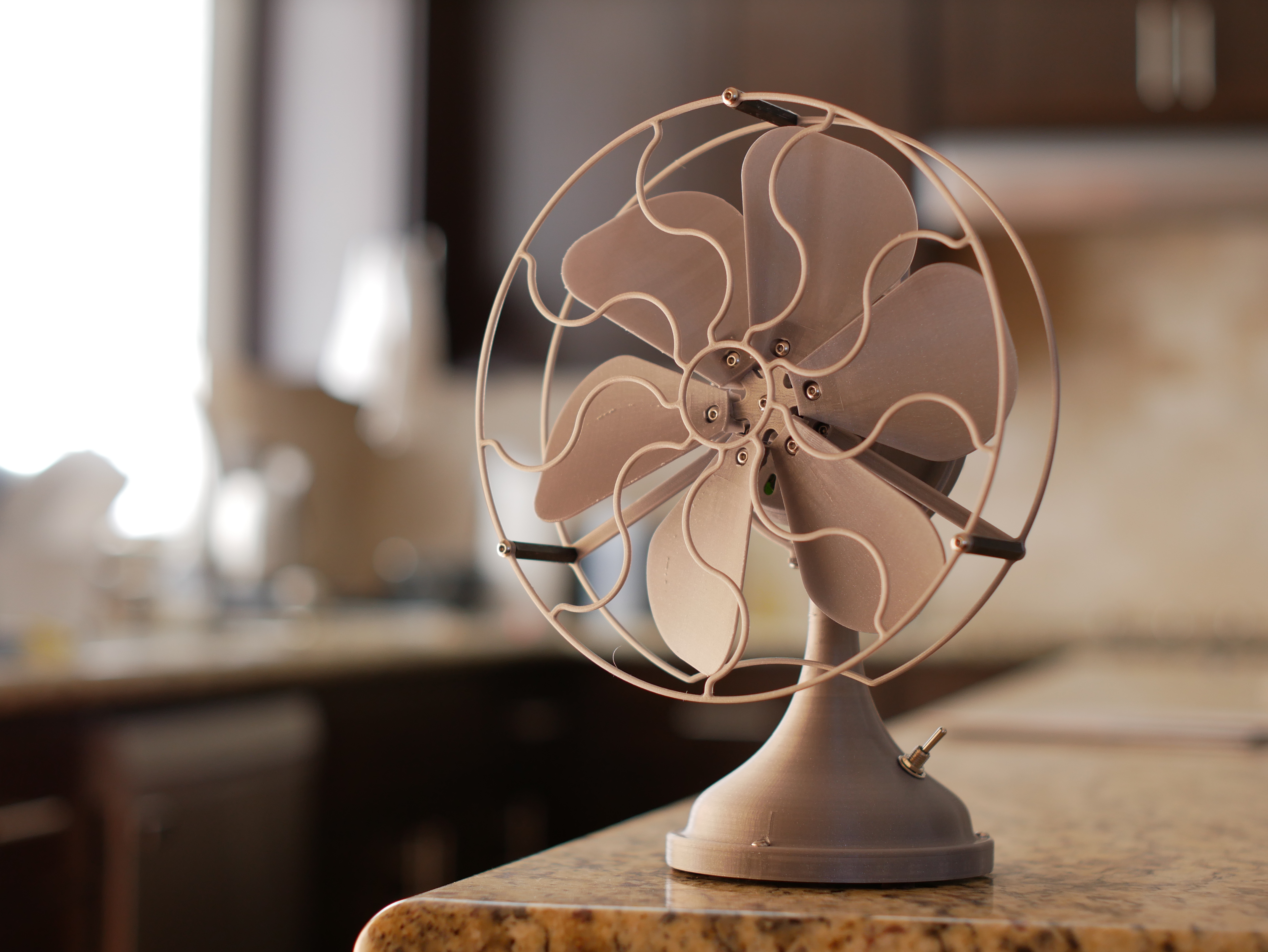
<h5>Overview</h5><p>This is a mini retro-styled desk fan that has a functional oscillation mechanism. The design is a complete rework of my older oscillating fan model.</p><figure class="media"><oembed url="https://youtu.be/-ohtJsWHgYk"></oembed></figure><p>It uses a common 130 size brushed hobby motor and incorporates an 18650 battery in its base for completely portable operation. Compared to the older design, the new version has significant internal changes, resulting in much quieter operation and an easier assembly process.</p><p>Fusion 360 model link: <a href="https://a360.co/3g4nEfN">https://a360.co/3g4nEfN</a></p><h5>Changes</h5><ul><li>All fasteners standardized to M3x10 bolts and locknuts.</li><li>Reprofiled base to fit standard 18650 battery holders, instead of requiring a lithium pouch cell. Battery life should be much longer as a result.</li><li>Main shaft gear is now an internal gear of a much larger diameter, with curved spokes to reduce noise transfer. Motor pinion gear has a small cutout to achieve a similar effect. </li><li>Motor/shaft drive gears now have larger teeth, requiring less precise clearances. </li><li>Motor mount redesigned to allow adjusting gear clearance. Attachment points have been thinned out to reduce noise, with a TPU-specific variant available for even lower noise levels. </li><li>Redesigned blade assembly with individually adjustable fan blades. Blades are much wider and have greater camber, reducing noise and moving more air. Subjectively, they look a lot better too. </li><li>Front housing extended rearwards, with motor mount attaching directly to it instead of being sandwiched between front/rear shells. Allows opening up the housing without the motor mount coming out.</li><li>Rear housing bolts are now exposed on the outside of the housing, instead of being hidden inside, for much easier housing assembly.</li><li>Added a springy cutout at the bottom of the loop/handle component to reduce noise transferred to the base.</li></ul><h5>Recommended filaments</h5><ul><li>Standard PLA/PETG/ABS for the main body parts and oscillator gearbox<ul><li>Important note: certain filaments have much more friction than others, such as the Prusament Galaxy Silver I used for the exterior parts. In this case you'll want to print all the internal oscillator parts out of a filament with a more slippery filament.</li></ul></li><li>TPU strongly recommended for certain parts to reduce noise levels. These include the main and motor pinion gears as well as the motor mount. Optionally the mid shaft, front shaft, and oscillator screw can also be made in TPU to reduce rattles.<ul><li>TPU-specific variants of the front shaft and motor mount are provided in the files.</li></ul></li></ul><h5>Parts</h5><ul><li>130 size hobby motor. Try to find a low RPM motor rated for higher voltage (6V/12V). The typical 1.5/3v ones spin too fast with too little torque to work well with this design, and may overheat and burn.<ul><li>For a good quality option, the Mabuchi FK-130SH has carbon brushes and is rated 7200RPM@12V. It runs quieter than the generic hobby motors.</li></ul></li><li>608 bearings (x2)</li><li>18650 battery and holder</li><li>Mini toggle switch with 6mm/0.25" thread diameter</li><li>TP4056 charging board<ul><li>A small heatsink is highly recommended - these cheap charger boards get extremely hot in certain circumstances</li></ul></li><li>Adjustable boost converter (2-24V) - highly recommended to better tune the motor speed. If your motor runs at an appropriate speed at normal battery voltage, this isn't needed.</li><li>M3 locknuts (x25)</li><li>M3x10mm button head bolts (x32)</li><li>35mm nylon standoffs (x3)<ul><li>Printed standoffs can also be used</li></ul></li><li>Mini felt or rubber feet (x3)</li><li>Hot glue, wires, etc.</li></ul><h4>Printing recommendations</h4><ul><li>Print all the TPU parts individually, in particular the rotating shaft components and gears, to reduce stringing.</li><li>Depending on your bed surface, the oscillator arm and handle will likely need a brim to keep them stuck down.</li><li>Part clearances have been optimized for my own printer and will probably need adjusting.</li><li>For the cleanest surface finish, I used 0.1mm layers. Anything from 0.05-0.2mm should be fine for this design.</li></ul><p> </p><h3>Build Guide</h3><p>This build has a decent number of moving parts, but assembly should be relatively straightforward. All bolts are the same length, so no need to worry about which ones go where.</p><p>Small note: the pictures below may have some older versions of parts, so don't worry about them looking different. The assembly process should be the same. </p><p>Let's start with wiring:</p><figure class="image image-style-align-center image_resized" style="width:50%;"><img src="https://media.printables.com/media/prints/317554/rich_content/156180e0-fe58-489b-ac5e-133950191c8d/p1060165.jpg#%7B%22uuid%22%3A%22d67ab505-0edb-4b26-9f46-e9ac0686d4a4%22%2C%22w%22%3A4592%2C%22h%22%3A3448%7D"></figure><p>Solder the battery holder to the corresponding battery terminals on the charging board. Solder the switch to the positive output of the charging module. Solder the negative input of the boost converter to the negative output of the charging board, and solder the positive input of the boost converter to the other side of the switch. If not using a boost converter, just leave two long lengths of wire. At this point, the switch can be screwed into the base, but <strong>do not solder the motor to the wire leads</strong> - they'll need to pass through the housing and base first. Thread the wires through them as shown:</p><figure class="image image-style-align-center image_resized" style="width:50%;"><img src="https://media.printables.com/media/prints/317554/rich_content/ebae364b-6179-41e7-964c-090df7786b05/p1060185.jpg#%7B%22uuid%22%3A%223e3adce0-7143-4c24-ae54-c2e7621d30d9%22%2C%22w%22%3A4592%2C%22h%22%3A3448%7D"></figure><figure class="image image-style-align-center image_resized" style="width:50%;"><img src="https://media.printables.com/media/prints/317554/rich_content/535cb4d7-75ae-4af0-a7f7-d58b91718db9/p1060187.jpg#%7B%22uuid%22%3A%22d0a648de-23f9-4941-9ae9-93a5bfe73a6d%22%2C%22w%22%3A4592%2C%22h%22%3A3448%7D"></figure><p>Once the wires are threaded through the base and housing, the motor can be soldered onto the end. To more easily see the direction the motor is spinning, install the motor pinion onto the motor shaft before soldering the motor. When looking from the shaft side, it should be turning clockwise.</p><figure class="image image-style-align-center image_resized" style="width:50%;"><img src="https://media.printables.com/media/prints/317554/rich_content/2298c831-e2b7-4d58-aaea-2ba6a742ec14/p1060189.jpg#%7B%22uuid%22%3A%228f1e0c76-f782-4604-abc5-952918c8b86d%22%2C%22w%22%3A4592%2C%22h%22%3A3448%7D"></figure><p> </p><p>We can now move onto the main assembly. Assemble the blades onto the hub using a nut and bolt each. Note that the blades can slide in or out a few mm; you should start with them moved all the way inward. Later on they can be individually adjusted to balance the blade set. Set the blades aside for now.</p><figure class="image image_resized" style="width:50%;"><img src="https://media.printables.com/media/prints/317554/rich_content/ce22af7c-ab2b-4336-94ba-65708bd06486/p1060182.jpg#%7B%22uuid%22%3A%22fbc55178-34a0-4c3c-ba9a-fa2eceba4583%22%2C%22w%22%3A4592%2C%22h%22%3A3448%7D"></figure><p> </p><p>If you haven't done so yet, press fit a bearing into the front housing:</p><figure class="image image-style-align-center image_resized" style="width:50%;"><img src="https://media.printables.com/media/prints/317554/rich_content/c4467159-a546-4815-a06f-24e5d8817d65/p1060171.jpg#%7B%22uuid%22%3A%2294e7968f-e467-46f1-8487-cd5b6a53ad27%22%2C%22w%22%3A4592%2C%22h%22%3A3448%7D"></figure><p> </p><p>Attach the rear grille to the front housing using 3 bolts and lock nuts:</p><figure class="image image-style-align-center image_resized" style="width:50%;"><img src="https://media.printables.com/media/prints/317554/rich_content/f40fe708-3781-40cc-9d58-4301b25221a2/p1060194.jpg#%7B%22uuid%22%3A%22be250cdf-8c9a-4526-85c3-4ec523b18bc2%22%2C%22w%22%3A4592%2C%22h%22%3A3448%7D"></figure><p>Next, assemble the front shaft and main gear as shown below:</p><figure class="image image-style-align-center image_resized" style="width:50%;"><img src="https://media.printables.com/media/prints/317554/rich_content/f6326879-44bb-4915-bc4b-0d00d130fe8f/p1060190.jpg#%7B%22uuid%22%3A%222d7757f5-261a-49f8-8e70-938dab18a778%22%2C%22w%22%3A4592%2C%22h%22%3A3448%7D"></figure><figure class="image image-style-align-center image_resized" style="width:50%;"><img src="https://media.printables.com/media/prints/317554/rich_content/93710eeb-0194-4872-92dd-0d662f72573e/p1060192.jpg#%7B%22uuid%22%3A%2264430998-def3-4ae4-96a5-04ccaf3fc032%22%2C%22w%22%3A4592%2C%22h%22%3A3448%7D"></figure><p> </p><p>Insert the assembly into the front housing. Note that you may need to move the front shaft back a bit so that the gear can move into the correct position:</p><figure class="image image-style-align-center image_resized" style="width:50%;"><img src="https://media.printables.com/media/prints/317554/rich_content/5052ac8c-4ba6-419f-949f-ed288054f9a1/p1060196.jpg#%7B%22uuid%22%3A%2280f4e445-0591-4f38-880c-685728d2b084%22%2C%22w%22%3A4592%2C%22h%22%3A3448%7D"></figure><p> </p><p>Motor mount assembly is next:</p><figure class="image image_resized" style="width:50%;"><img src="https://media.printables.com/media/prints/317554/rich_content/c38b78ae-a25f-481d-bb4c-39ce417f11b1/p1060197.jpg#%7B%22uuid%22%3A%22dc6d833c-cbc9-4b58-8ea2-8fdefeb89940%22%2C%22w%22%3A4592%2C%22h%22%3A3448%7D"></figure><p>Insert the motor into the mount and tighten down the clamping screw to the immediate right of the motor. The mid left screw will be used for gear clearance adjustment, so just tighten until you feel the resistance of the lock nut for now. </p><p>Insert a lock nut into the bottom left and bottom right slots of the housing, and screw the motor mount in (not shown). At this point, the blades can also be attached onto the front shaft with a single bolt. This bolt screws directly into the front shaft plastic, so take care not to overtighten.</p><figure class="image image_resized" style="width:50%;"><img src="https://media.printables.com/media/prints/317554/rich_content/ebcbeb70-94b8-4e10-bce8-e2e467ae56cd/p1060201.jpg#%7B%22uuid%22%3A%220f459412-c65b-43cc-a3d6-a87f0ae0855c%22%2C%22w%22%3A4592%2C%22h%22%3A3448%7D"></figure><p> </p><p>Now for the oscillator gearbox and rear housing. The rear bearing presses in first:</p><figure class="image image-style-align-center image_resized" style="width:50%;"><img src="https://media.printables.com/media/prints/317554/rich_content/fa2893ec-86ed-41cd-8e35-3f974d67a9ef/p1060206.jpg#%7B%22uuid%22%3A%2268eea29c-cb39-4b7a-a8cc-df8d8ca40e1f%22%2C%22w%22%3A4592%2C%22h%22%3A3448%7D"></figure><p> </p><p>The collection of oscillator parts is shown below:</p><figure class="image image-style-align-center image_resized" style="width:50%;"><img src="https://media.printables.com/media/prints/317554/rich_content/9fecc249-c75a-48be-986c-dd26aae102b4/p1060209.jpg#%7B%22uuid%22%3A%2208f1472e-b250-4b80-8a6a-30f97e6c2c7e%22%2C%22w%22%3A4592%2C%22h%22%3A3448%7D"></figure><p> </p><p>Insert the end gear into the mid frame, and place a lock nut into the top of the end gear:</p><figure class="image image-style-align-center image_resized" style="width:50%;"><img src="https://media.printables.com/media/prints/317554/rich_content/55c2afec-a992-44d0-a4a2-98f9ef9ba237/p1060213.jpg#%7B%22uuid%22%3A%2229c4663c-8d28-4cdd-a075-25d65ff7a221%22%2C%22w%22%3A4592%2C%22h%22%3A3448%7D"></figure><p> </p><p>Take the mid gear and attach it as shown using the mid gear pin. The larger diameter side of the mid gear should be facing up.</p><figure class="image image_resized" style="width:50%;"><img src="https://media.printables.com/media/prints/317554/rich_content/ee452e73-341b-491b-b889-39b85633114d/p1060214.jpg#%7B%22uuid%22%3A%226b8eb68e-9a99-4d3e-b9aa-e29d50d987d1%22%2C%22w%22%3A4592%2C%22h%22%3A3448%7D"></figure><p> </p><p>Insert a bolt through the bottom of the slide gear as shown:</p><figure class="image image_resized" style="width:50%;"><img src="https://media.printables.com/media/prints/317554/rich_content/03e295d2-d59c-4ed5-93b4-56b09bef2c91/p1060216.jpg#%7B%22uuid%22%3A%22f13ee7f8-d042-44ec-887e-64ca10144228%22%2C%22w%22%3A4592%2C%22h%22%3A3448%7D"></figure><p> </p><p>Stick the slide gear and bolt onto the slide gear frame:</p><figure class="image image_resized" style="width:50%;"><img src="https://media.printables.com/media/prints/317554/rich_content/8525017d-4b27-478b-8ca1-ae631c57ae23/p1060217.jpg#%7B%22uuid%22%3A%2257492559-bf61-42ec-b35a-239c2fdb20d3%22%2C%22w%22%3A4592%2C%22h%22%3A3448%7D"></figure><p> </p><p>Below shows the complete gearset. Set these parts aside for now.</p><figure class="image image_resized" style="width:50%;"><img src="https://media.printables.com/media/prints/317554/rich_content/d027f15c-84fc-454c-8733-07cfeef6632d/p1060218.jpg#%7B%22uuid%22%3A%2270997d8d-2324-4de9-9f11-a22e6832c970%22%2C%22w%22%3A4592%2C%22h%22%3A3448%7D"></figure><p> </p><p>Take the oscillator knob and insert it into the slot on the housing:</p><figure class="image image_resized" style="width:50%;"><img src="https://media.printables.com/media/prints/317554/rich_content/6c2c7201-a562-46b2-916a-f2448d99017a/p1060219.jpg#%7B%22uuid%22%3A%2289f560c2-fb20-416f-af63-2393bb459787%22%2C%22w%22%3A4592%2C%22h%22%3A3448%7D"></figure><p> </p><p>Slide a lock nut into the slot on the inner section of the oscillator knob. Note that the threaded end (the side without the nylon) should be facing down, as shown:</p><figure class="image image_resized" style="width:50%;"><img src="https://media.printables.com/media/prints/317554/rich_content/9479513d-f86e-416d-b0a9-9b6050b19bad/p1060220.jpg#%7B%22uuid%22%3A%2276f03d6f-8e65-4274-9f8a-4aef97fb5384%22%2C%22w%22%3A4592%2C%22h%22%3A3448%7D"></figure><p> </p><p>Pull the oscillator knob upwards so the bottom is flush with the housing, and twist it 90 degrees to lock it in place to prevent the lock nut from falling out:</p><figure class="image image_resized" style="width:50%;"><img src="https://media.printables.com/media/prints/317554/rich_content/d073a586-8be3-4119-a480-f6f5006fafce/p1060221.jpg#%7B%22uuid%22%3A%229f978281-4564-4812-81ea-7d25823938e8%22%2C%22w%22%3A4592%2C%22h%22%3A3448%7D"></figure><p> </p><p>Carefully slide the gearset into the oscillator housing:</p><figure class="image image_resized" style="width:50%;"><img src="https://media.printables.com/media/prints/317554/rich_content/0b653366-ad27-46ca-b439-b39985b478b0/p1060222.jpg#%7B%22uuid%22%3A%22affba7a9-68f9-48c7-b371-944e87e1e7fd%22%2C%22w%22%3A4592%2C%22h%22%3A3448%7D"></figure><figure class="image image_resized" style="width:50%;"><img src="https://media.printables.com/media/prints/317554/rich_content/9f0495bd-585d-4766-8adf-47e0f0753dc8/p1060223.jpg#%7B%22uuid%22%3A%229ef6fb8e-b844-4694-bbaf-be9439bed091%22%2C%22w%22%3A4592%2C%22h%22%3A3448%7D"></figure><p> </p><p>Use a hex key to tighten the slide gear bolt into the oscillator knob lock nut. Tighten all the way and then back off about half a turn. Verify that the slide gear is free to turn, and that the oscillator knob can pull the gear up and down. Also make sure that the knob loosely locks in place when turned sideways, preventing the gear from sliding back down.</p><figure class="image image_resized" style="width:50%;"><img src="https://media.printables.com/media/prints/317554/rich_content/87cc8abd-33c1-4c9d-b6f7-8e72115bfe80/p1060224.jpg#%7B%22uuid%22%3A%225af054db-f526-4f4a-b5e6-a4641bfb24f5%22%2C%22w%22%3A4592%2C%22h%22%3A3448%7D"></figure><p> </p><p>Bolt the oscillator gear to the end gear from below. This step is a bit finicky as you'll need to use a finger to hold the gears steady while tightening.</p><figure class="image image_resized" style="width:50%;"><img src="https://media.printables.com/media/prints/317554/rich_content/df35eb2b-f087-4a8b-8b46-9ee3f7f29968/p1060226.jpg#%7B%22uuid%22%3A%2223d2d8a9-447d-4b89-873f-40bad9a2c65b%22%2C%22w%22%3A4592%2C%22h%22%3A3448%7D"></figure><p> </p><p>Use two nuts and bolts to attach the oscillator to the rear housing:</p><figure class="image image_resized" style="width:50%;"><img src="https://media.printables.com/media/prints/317554/rich_content/91000f34-9bd4-4259-a03e-214fa9b36b23/p1060228.jpg#%7B%22uuid%22%3A%22b07d55c2-f328-43af-96d9-d947c9f69bbf%22%2C%22w%22%3A4592%2C%22h%22%3A3448%7D"></figure><figure class="image image_resized" style="width:50%;"><img src="https://media.printables.com/media/prints/317554/rich_content/f5f1ded9-66a1-4411-a0be-0b043f440efb/p1060230.jpg#%7B%22uuid%22%3A%22b5468a89-eab3-4081-ab6e-3355b92f0056%22%2C%22w%22%3A4592%2C%22h%22%3A3448%7D"></figure><p> </p><p>I forgot to take pictures of the next few steps, but they should be straightforward. Insert the oscillator screw into the rear bearing. Insert the mid shaft into the front shaft, and then attach the rear housing onto the front housing and secure with two bolts on either side of the rear housing. Make sure the mid shaft is slotted into both the front shaft and the oscillator screw, and verify the blades turn smoothly with little resistance.</p><p>Also not shown: Pull the loop handle over the motor housing from the rear side. the two pins on the top and bottom should slot into the holes on the front housing. Then attach the handle to the base with a nut and bolt.</p><p>Afterwards, attach the oscillator arm to the crank and the handle as shown below, and attach the front cage with some standoffs.</p><figure class="image image_resized" style="width:50%;"><img src="https://media.printables.com/media/prints/317554/rich_content/f1a3d521-a189-4ae7-84dc-f19087c859f6/p1060247.jpg#%7B%22uuid%22%3A%229b19c47f-999d-4184-928d-25f163c34d36%22%2C%22w%22%3A4592%2C%22h%22%3A3448%7D"></figure><p> </p><p>Just a few more steps to go. Hot glue all the electrical components onto the bottom plate, making sure that the charging board is correctly positioned at the rear against the cutout for the charging connector. The battery holder should be approximately in the middle so that it fits under the base without touching.</p><p>Turn the fan on for a test run, and screw the bottom cover onto the base if everything's working properly.</p><figure class="image image_resized" style="width:50%;"><img src="https://media.printables.com/media/prints/317554/rich_content/7300ad83-9317-4930-b340-80c68636f478/p1060238.jpg#%7B%22uuid%22%3A%22223156a7-e441-4cb3-a3fe-fe712aaaa8d7%22%2C%22w%22%3A4592%2C%22h%22%3A3448%7D"></figure><p> </p><h4>Adjustment and troubleshooting</h4><ul><li>Motor speed<ul><li>If using a boost converter, make sure to tune the voltage setting so that the fan spins at the desired speed. Be wary of overdriving the motor—these little 130 motors don't have much power at all—and open up the housing to check that it isn't getting too warm.</li><li>If the motor twitches on startup and stops, you're tripping overcurrent protection on the charging board. Lower the motor speed and/or check for excessive friction in the gear drive and oscillator.</li></ul></li><li>Gear adjustment<ul><li>There's a sweet spot, where the motor pinion is gliding over the main gear without pushing into it, that makes for the quietest operation. You can turn the adjustment screw on the motor mount to move the motor pinion up or down. If raised up too much, the gears will slip on startup. If you get to this point, lower the pinion down by loosening the tensioner screw by a few turns.</li></ul></li><li>Blade balance<ul><li>The front shaft should fit very snugly into the front bearing. If it's sloppy, the blade hub won't be totally centered.</li><li>Hub center screw should be tight, but don't overtighten, as you'll strip the plastic out of the front shaft.</li><li>Verify all blades are tight. If they are and the whole blade assembly can tilt a significant amount, you may need a higher quality front bearing.</li><li>If the above have been verified and there's still too much imbalance, the blades can be slid in and out for balance adjustment. Not sure about the best process for this though; it might be mostly trial and error.</li><li>Note that due to printing tolerances, a small amount of wobble will likely remain present. This shouldn't affect normal operation.</li></ul></li><li>Excessive noise<ul><li>Use TPU for the recommended parts if you can, otherwise it'll run loudly</li><li>Adjust the motor gear clearance</li><li>Make sure the blades are relatively balanced</li><li>Reduce the fan speed</li><li>If the base is resonating (check by pressing down hard on it and seeing if it quiets down), it might help to stuff it full of something that dampens sound, like cotton balls. This will likely only make a small difference though.</li></ul></li><li>When oscillator is engaged, fan slows down a lot<ul><li>It's normal for the fan to slow down when the oscillator is engaged, since it now has to push the entire fan assembly back and forth. If slowing down a lot, there may be excessive friction.</li><li>Make sure the housing turns completely freely in the loop. If you printed the handle piece with a brim, be sure it's completely removed around the parts where the housing connects.</li><li>Make sure the slide gear isn't overtightened onto the oscillator knob, and make sure both ends of the oscillator arm are only loosely screwed in.</li><li>Make sure the oscillator gears and the slide frame are printed in a slippery filament. Solid color PLA/PETG/ABS should be fine for the most part, but certain colors with additives may have more friction. As an example, the Galaxy Silver I used has some shiny particles embedded that gives it noticeably higher sliding friction.</li><li>The oscillator screw needs to be smooth, and the overhangs shouldn't droop. You may need to print at a lower temperature and increase cooling if the threads look messy.</li><li>A small dab of grease on the oscillator gears and screw may help, but I haven't tried. Don't grease the main/motor gears, as it'll just fling out and make a mess of the inside of the housing.</li></ul></li></ul>
With this file you will be able to print Retro Oscillating Fan - Redux with your 3D printer. Click on the button and save the file on your computer to work, edit or customize your design. You can also find more 3D designs for printers on Retro Oscillating Fan - Redux.