RetroPie Bartop Arcade Cabinet
thingiverse
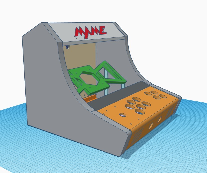
This text appears to be a manual or guide for building a custom arcade cabinet using a Raspberry Pi as the main component. The author provides a list of required materials and tools, as well as detailed instructions on how to assemble the cabinet. Here are some key points from the text: **Required Materials:** * Raspberry Pi 2 or 3 with minimum of 16GB micro SD * USB flash drive for storing ROMs * Various cables (depending on setup) * Primer and paint (optional) * Time and patience **Display Requirements:** * Maximum display width is 350mm * Aspect ratio of 4:3 produces best results * Many new and used 4:3 displays can be found on Ebay **Assembly Instructions:** 1. Lay one of the sides down and attach the monitor mount to the display. 2. Epoxy the monitor side supports to each cabinet side. 3. Remove the display and epoxy the monitor mount to the supports and sides as illustrated. 4. Re-attach the monitor and then epoxy the monitor BOTTOM supports in place. 5. Allow plenty of time to cure. 6. Turn the cabinet on its side and mock up the marquee support. 7. Epoxy the marquee supports into place. 8. After curing, the marquee should rest nicely on these supports and can be epoxied into place. 9. Mock up the control panel with the cabinet upright and then epoxy the 2020 extruded aluminum models into place. 10. Wire up the control panel and attach to the 2020 models using M4 bolts and T-nuts. 11. Epoxy the hinged back door BOTTOM and the bottom support piece into place. 12. After curing, attach the 3D-printed hinges and back door. **Tips and Notes:** * Sand every joint where epoxy will be applied to ensure a strong bond. * Use the T-nuts and M4 bolts to attach the panel after the epoxy cures. * The monitor viewing angle is 36 degrees, which may affect the placement of the monitor mount and supports. * Vents on the control panel are ideal for adding stereo speakers. * SVG files are supplied for alternative marquee themes. Overall, this text provides a comprehensive guide for building a custom arcade cabinet using a Raspberry Pi as the main component. The author assumes that the reader has some basic knowledge of 3D printing and electronics, but provides detailed instructions on how to assemble the cabinet.
With this file you will be able to print RetroPie Bartop Arcade Cabinet with your 3D printer. Click on the button and save the file on your computer to work, edit or customize your design. You can also find more 3D designs for printers on RetroPie Bartop Arcade Cabinet.