Revised G Scale LGB Servo Coupling
thingiverse
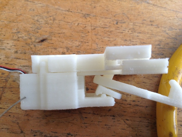
UPDATE: After using this for a while I have noticed that setting the engaged and uncouple positions on the servos is very critical. If the servo is too far "engaged", (ie pulled "back" ) then the hook cannot spring down to couple easily. Also, if the Unlock position was too far "forward", then the hook on the carriage could get caught behind the front part of the pusher. To overcome this, I have modified the design by removing the front of the pusher entirely. I then modified the hook, to keep its geometry when engaged roughly the same. (see new file "hook3" ). Without the front bar of the pusher it now disengages very reliably. (see "mk3 pusher"). The original reason for the front part of the pusher was to provide a removable lip to keep the hook of the carriage engaged, but with the hook from the loco engaging in the carriage, there seems little point in this, so I removed it and will see how well it works on the track. It certainly decouples very easily and the "engaged" servo position now seems much less critical. Please send feedback if you have any improvements. video with full design working decoupling from a carriage (servos set correctly!) ... https://www.youtube.com/watch?v=UJGuc5AQuE4 The parts Loop2 Pusher2 and Base2 are very slight modifications on the original (still available in the 123D file) based on my building the first "production run".. I have found that it now works well with the same magnets in the loop and hook - so you can use 3 mm dia * 4 mm long magnets in both parts. The Mk3 version also uses this larger magnet This is a complete revision of my earlier (http://www.thingiverse.com/thing:398423) and http://www.thingiverse.com/thing:377751 couplings. The main benefit is that the hook is now free to move in the horizontal axis, which should make the coupler work better around corners. I have also revised the servo's housing, and it now allows space for the wires connected at the bottom!. The new magnets hold the hook firmly in the centre , "engaged" position, but allow the hook to engage with another carriage when they are pushed together, and completely replaces the difficult to adjust springs in previous versions. As the pusher pushes forwards, the pivot pushes forwards and tilts down, pulling the hook away from loop and de-coupling.. Thingyverse seems to have lost my old "how to assemble" text but it is relatively straightforward. after cutting off the pusher plate arms, assemble the servo in the main housing, and hold it in place with a wire like in the photo. Then take the hook and the pin and the pusher pllate and assemble them to the servo. The pusher plate should fit firmly on the servo horn. If necessary, some filing will help here. Also, the servo horn may need to be cut down so it does not touch the main Eye body when assembled. Assuming you have the magnets correctly installed in the eye and hook, you can first fit the eye to the loco and then carefully fit the servo/housing/ pin hook assembly to the eye. The hook will try to magnetically snap to the eye, so be careful. Make sure you test for movement at this stage with a servo tester. If all goes well, screw the small 10mm screws into the housing to hold it to the eye body that is connected to the loco. The photos on my older design (https://www.thingiverse.com/thing:398423) show the assembly process quite nicely.
With this file you will be able to print Revised G Scale LGB Servo Coupling with your 3D printer. Click on the button and save the file on your computer to work, edit or customize your design. You can also find more 3D designs for printers on Revised G Scale LGB Servo Coupling.