Ring light for stereo microscope with 48mm thread, Olympus and others
prusaprinters
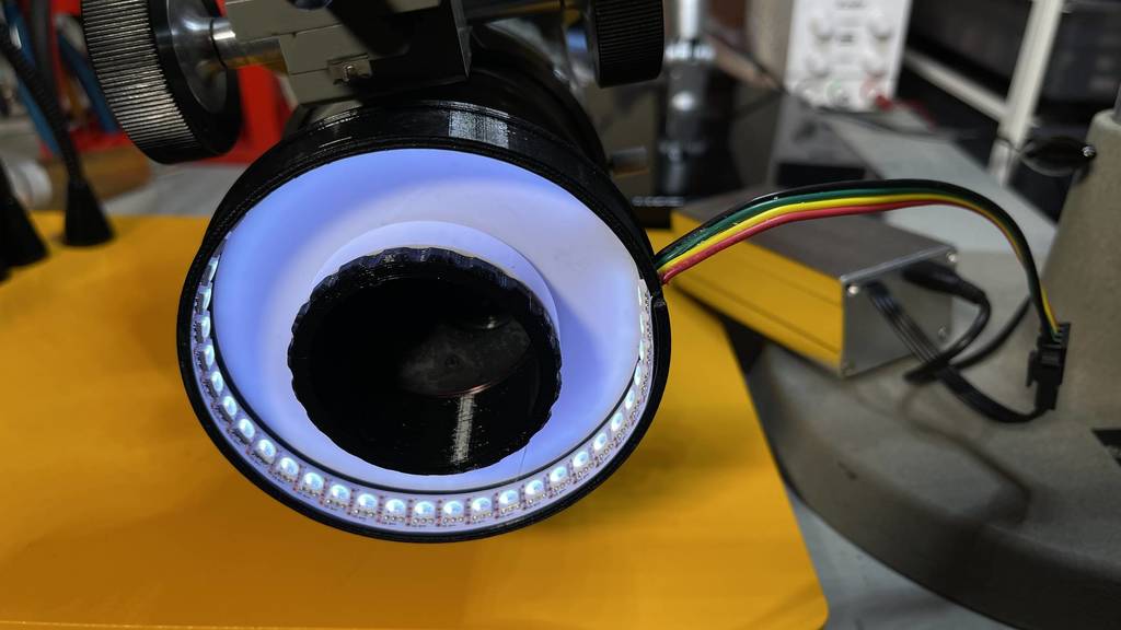
<p>This is an Arduino-controlled ring light for stereo microscopes with a 48x0.75mm threaded nose piece. This is one of the most common sizes and fits my vintage Olympus unit. Other thread sizes for which commercial ringlight adapters are available are 52, 55 and 58mm. This design can also be used for a camera ringlight; the parameterization should help you adapt it to almost any lens/filter thread size.</p><h3>Inspiration</h3><p>My microscope is 50 years old and never had a ring light, and it really needed one.</p><p>The build was inspired by a couple of YouTube videos and a Thing from Otinex that showed you can print 48x0.75mm male threads that successfully fit into a microscope nosepiece. I was skeptical but printed one and it worked quite well. Alas there was no CAD file and I wanted to do several things differently, so I had to do an all-new mechanical setup.</p><p>My design uses the DotStar LED strips from Adafruit, with an Arduino Metro Mini to drive them. The DotStar is a modern successor to the older fixed-clock NeoPixels and will accept a much higher synchronous data clock, making them truly flicker-free.</p><h3>Mechanical</h3><p>Pre-made flat rings of DotStars aren't available so I used the 144/meter strip to form a cylinder with the LEDs facing inwards. White plastic is used where reflectivity is helpful to put more light on the target; this includes the thin reflector plate and the spacer ring. Black plastic is used for everything else to block light from entering the objectives or going directly up into the user's face. Optically there is no direct path from any LED into the objectives, even though the LEDs are facing inward.</p><p>I used a strip of 40 LEDs to form a roughly 93mm circle. As it turned out I could have used 42, or reduced the diameter of the circle slightly.</p><p>You do need to cut a slot in the side of the cylinder to bring out the rather heavy gauge 4-conductor cable. I chose not to print the cylinder with the slot in place so the ring would be a complete circle during printing. The slot is about 3mm wide; I used a saw blade in a Dremel tool. Some parts are glued together using Plasti-Zap, which is a plastic bonding super glue.</p><p>The cylinder is glued into the top cap, and the white reflecting plate is glued to the top cap <i>before</i> the LEDs are installed. Cut the slot after these first three parts are glued up.</p><p>Finally the LED strip is glued to the inside of the black cylinder with the cable routed out through the slot.</p><p>Here is the OnShape CAD file: <a href="https://cad.onshape.com/documents/cb052133db7924fde58ad412/w/585d470d4f1ae3a4aa7b4591/e/4b52144fad6a23b9d824eaa9">https://cad.onshape.com/documents/cb052133db7924fde58ad412/w/585d470d4f1ae3a4aa7b4591/e/4b52144fad6a23b9d824eaa9</a></p><p>Nearly everything is parameterized in the "globals" feature studio tab, so it's trivial to change the diameter of the ring, make the spacer longer/shorter, modify the length of the screw section, etc. to suit your particular application.</p><p>To add the 0.75mm pitch threads, you need to use the "ThreadCreator" custom feature in OnShape - add this to your workspace using the "Add custom features" tool, switch to the "other documents" tab and search for ThreadCreator.</p><h3>Printing</h3><p>There is nothing special about the printing - just be sure to use white for the reflector disc and the spacer ring. You can use any fairly opaque color for the other parts. I recommend PETG over PLA for this application; at max brightness the LED strip makes things pretty warm and it might approach the sag temperature for PLA.</p><h3>Electronics</h3><p>The controller for the LEDs is nothing more than an Arduino Metro Mini, a pair of 10K pots, a connector matching the cable, and a power supply. You only need two GPIO outputs for bit-banging the clock and data down to the LED strip, and 2 analog inputs to read the color and intensity pots. The code size is small enough that you can use just about any Arduino in existence. I prototyped the HW on a plug-in breadboard; the final controller was soldered up on a "half size" perma-proto board.</p><p>You do have to be quite careful about the power draw. This many DotStars will consume around 2 Amps at full intensity, which is too much to pull through a typical USB hub when debugging with the computer attached. I put some compile-time switches in the firmware to limit the intensity to about 1/8 of the max while testing. To power the unit for actual operation I'm using a 2.5A micro USB wall adapter, which will happily run the LEDs at full blast. It's important to get the power directly from the USB source and not try to use the Arduino's 5V regulated power, which is limited to 500mA.</p><h3>Electronics Packaging</h3><p>My microscope doesn't have any good flat surface where I could attach the controller box, so the control box needs to sit on the desk and be hefty enough to prevent it from getting dragged around by the cords. I ended up using a commercial all-aluminum split-case project box (see BOM below) with an added block of aluminum inside to bring the total mass up to about 175 grams. The electronics board is mounted to the top of the 18mm thick aluminum block with 3 4-40 (or M3) screws, using 1/4" (6mm) nylon standoffs.</p><p>To make the half-size perma-proto board fit, I needed to cut off the power/ground rows on one side. (Hint: wet tile saws are the greatest thing ever if you need to cut any amount of fiberglass circuit board or similar composite sheets!)</p><p>One end panel of the Eightwood case was drilled for the two pots, and the other end was CNC milled with an access slot for the micro-USB connector, and a slot for the 4-conductor output cable. This was just done to measure, so there's no CAD file - sorry!</p><h3>Firmware</h3><p>The firmware is a regular Arduino sketch made using the Arduino IDE. The excellent FastLED library is used to control the DotStar LEDs. It handles bit-banging the data down the LED chain so you don't have to write code for that. Reading the pots uses the built-in analogRead() from the standard Arduino libs.</p><p>Two knobs are supported - an intensity knob and a color knob. When the color knob is turned off (full counter-clockwise), the light operates in bright white intensity-only mode, with the brightness controlled by the intensity knob.</p><p>When the color knob is turned clockwise off zero, the code switches into HSV mode where the color knob controls the hue, and the intensity knob controls a blend of saturation and value. In this mode you will notice some color shift at low intensity, and the peak brightness achievable is somewhat less than if you're in white mode, but it does let you move around through a subset of HSV space with only two knobs.</p><p>I'm planning to add a photographic color-temperature mode, but I'm not sure the RGB DotStars will do it well.</p><p>The firmware is on GitHub here: <a href="https://github.com/dbcook/ringlight_arduino">https://github.com/dbcook/ringlight_arduino</a></p><h3>Bill of Materials</h3><p>Black PETG</p><p>White PETG</p><p>Eightwood aluminum case 4.33 x 2.01 x 1.5"</p><p>Aluminum block approx. 3.7" x 1.6" x 0.75"</p><p>4-40 x 1/4" flat-head machine screws, qty 3 to mount the aluminum block</p><p>4-40 x 1/2" round-head machine screws, qty 3 to mount the circuit board</p><p>#4 x 1/4" nylon standoffs, qty 3</p><p>micro USB cable to connect the Arduino to your computer for firmware loading</p><p>Electronic parts and power supply are from Adafruit:</p><p><a href="https://www.adafruit.com/product/2590">Arduino Metro Mini</a> </p><p><a href="https://www.adafruit.com/product/2329">DotStar LED strip, 1/2m, 144/meter RGB on white tape</a> </p><p><a href="https://www.adafruit.com/product/562">10k linear pots, qty 2</a> </p><p><a href="https://www.adafruit.com/product/2048">Knobs for the pots, qty 2 - choose your poison</a> </p><p><a href="https://www.adafruit.com/product/578">JST SM plug/cable pair</a> </p><p><a href="https://www.adafruit.com/product/1995">2.5A micro USB power supply</a> </p><p><a href="https://www.adafruit.com/product/1609">Perma-proto board, half size</a></p><h3>Print Settings</h3><p><strong>Printer Brand:</strong></p><p>Prusa</p><p><strong>Printer:</strong></p><p>I3 MK3S</p><p><strong>Rafts:</strong></p><p>No</p><p><strong>Supports:</strong></p><p>No</p><p><strong>Resolution:</strong></p><p>0.25, first layer 0.30</p><p><strong>Infill:</strong></p><p>20%</p><p><strong>Filament:</strong> any PETG</p><p>Black and white</p>
With this file you will be able to print Ring light for stereo microscope with 48mm thread, Olympus and others with your 3D printer. Click on the button and save the file on your computer to work, edit or customize your design. You can also find more 3D designs for printers on Ring light for stereo microscope with 48mm thread, Olympus and others.