ROB-O Junior FFF 3D Printer using 80/20s 10/10 (1"x1") extrusion
thingiverse
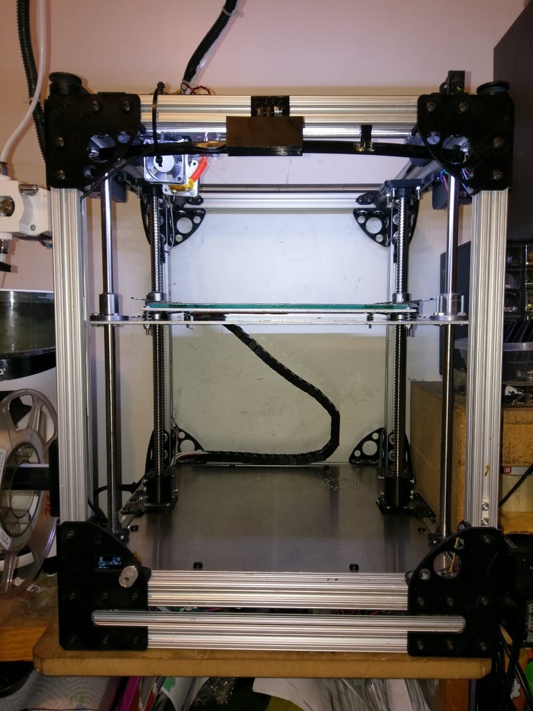
I know, I know, we need another 3D printer design like we need a hole in our heads but..... I love the Ultimaker with a passion, in my opinion it is THE printer to beat, it has the smallest layer height of a personal FFF printer I have found and in my drooling but lack of $2773 US dollars (at the moment) there was no way I could have one so at looking at it and dreaming of it I realized that I could do that and if I use a CoreXY mechanism I might even improve on it. so I made a scratch built printer from wood, nylon sheets, L shaped angle aluminum, wire ties and hot glue and it works really well but it could be better, you can see those exploits here http://rob-o-printer.blogspot.com/ I bought new printer parts to rebuild it but didn't want to tear it down so decided to take all the parts and use it to make a smaller printer and then use that printer to rebuild the bigger one so here it goes. I have everything designed, I have to print a couple more parts that I had to tweak but I will not add any parts to this that I have not printed and tested, so far the frame is done and I am working at printing some 12mm shaft clamps now to get the XY carriage installed into the frame so I can work out the motor mounts. In learning from my mistakes with ROB-O I am working at correcting them with R.J. btw I suck at names and was thinking robo printer but it exists but since my name is Rob I am going with Rob - O Printer until I can think of something better. So some differences between mine and Ultimaker besides the build volume is that I am using a CoreXY mechanism which Ultimaker has a unique way of getting some of the same properties in a smaller space. The other thing that I have learned and am excited to try that is different is getting the Z shafts and the Z screw off of the same plane, with them all being in a row it seems to cause more tension on the three, you are suspending a bed and just holding it on the edge with 3 shafts, on this design I am staggering the shafts and the screw pulling the Z shafts back a bit, that gives it a three point stand and that hopefully get rid of all the flex at the far end of the bed. I will let you know if that idea pans out. To get an idea of what it can do check this link out, it was done with the "Bubblegum" printer lol i.e. it is held together by bailing wire and bubblegum, if it can do this good of a job I can wait to see how well R.J. does as it has no slop in the heads at all. http://rob-o-printer.blogspot.com/2015/04/height-test.html My next update will be the CoreXY mechanism build. List of printed parts I have used so far. http://www.thingiverse.com/thing:980961 http://www.thingiverse.com/thing:980981 Dual CoreXY setup http://www.thingiverse.com/thing:990244 <b>Update 8/25/2015:</b> I added a couple pics of the corexy mechanism in place, it is not the final parts or final shafts but I wanted to get a better idea of where everything was going so used some test prints I had kicking around. The X carriage is printing now and it should be the final working version, if so I will post it as a separate thing, I left room for z probes etc. In the STL model is a version of the X and Y parts if you want a closer look for now. <b>Update 8/29/2015:</b> I finished my version of the CoreXY mechanism everything lines up and works now, I just need to make the corner bearing mounts and the motor mounts and it will be fully functional. <b>Update 9/11/2015:</b> I will be posting new pictures etc this weekend, I had to do a lot of rework on the coreXY mechanism, keeping the belt inside the frame hanging down was just not going to work with the corner pieces and were too big of a pain so I went with just the motors outside on the sides with the filament extruders and bearings in the corner, I reprinted the parts and everything is lining up, I just need to print some more bearing flanges and should have it all hooked up and hopefully wired together and printing this weekend. I will update the corexy with the new parts and the motor mounts probably tomorrow. <b>Update 9/25/2015:</b> I have everything hooked up but the hotends and the extruders and told it to print, told it to do a print speed of 150mm/s and a move speed of 300mm/s and it didn't blink an eye, I cranked it to 999% and it flew, I doubt it could push the plastic out that fast especially as I normally use a 0.3mm nozzle but the mechanism handled it just fine and flew, it was a glorious sight. <b>Update 9/26/2015:</b> I have it completely assembled and printing. It is printing beautifully, I am going to use it to reprint all the parts in the final colors then I will document the assembly, etc. when I put the new parts in, I may even do a build video or two. I ended up going with a silicone heat mat for the heat source it is the same price as the circuit board but much more efficient. <b>Update 10/12/2015:</b> Everything is up and printing and working nicely but I have encountered two issues. 1. Hotends get jammed. 2. Bed bounces. for #1 I had designed the fan to blow across and then the exit path for the air was up so it couldn't blow the hot air towards the plastic and I figured that was the cause of the jams so I opened it up to blow straight accross.... nope. I realized cura was retracting 16mm on hotend change, set it to 5 thinking it was pulling the molten plastic up too far... nope. I only printed with one hotend and everything worked flawlessly so I am thinking the fan is not blowing hard enough to cool both hotends so I ordered a 40mm x 40mm x 20mm fan that blows roughly 3 times more than the one I have, hopefully it will be here by the weekend, will update if that cures it. for #2 the shape of the bed is rectangular, the Z axis is on one of the short ends, if I was to put the Z axis on the side of the printer I would have to extend that side of the bed for it to reach and again would be causing it to be a rectangle held on the short end so there is a lot of bounce on the far end and I mean A LOT, every time the head moves the bed shakes. I ordered two 8mm shafts and bearings for the front corners of the bed, that SHOULD keep it from bouncing around and still allow it to move up and down, may have to have it home slower but printing at 0.2 - 0.02 layers like I normally do is slow enough for it not to bind during a normal print. I have the parts but have not had time to make it yet. I have had lots of ideas but this was the easiest, a great idea was to have a high 2" plate in the back top and bottom that then goes from their down each side tapering to the end of the bed but it would almost need to be one solid peice and it would add a lot of weight and the bed and build plate is heavy enough as it is. The Ultimaker has the same issue and the result is ghosting, on the ultimaker a lot of people slow down and print towards the Z mount, I want to find a way to let me print normally and get better results. All of that said I will probably make another corexy setup that is for 8mm shafts, I went 12mm because that is what I had on hand for my 20" print bed printer but for a smaller printer 12mm is mega overkill and add so much more weight, almost double the weight. <b>Update 10/17/2015</b> I managed to get rid of a good 80% of the bed bounce by just changing the Z motor coupler. I was using a flex coupler that I bought and it is cut like a spring so it could flex, problem is supporting the weight of the bed it also bounces up and down like a spring. I swapped it out for a solid coupler that I printed and most of the bed bounce is gone. I had left the top of the threaded rod open like Ultimaker but it wobbles a bit so I ordered a radial bearing today and will design a holder for it that will hold the other end solid but able to spin and I think the bed issues will be a thing of the past. The main issue is that the aluminum is so heavy I think I went too thick on the actual build plate so I think I am going to pick up a 3mm plate which will cut the weight by almost half which between that and the coupler/bearing should eliminate all of the bed bounce/z wobble. <b>Update 10/24/2015:</b> Added STL and SKP files for: Z-Motor mount Z-Motor coupler 12mm shaft mount 12mm cut down shaft mount for mounting the Y-axis shafts as close to the sides as I could. Z-axis bearing/bed holder designed for a 1/8" thick aluminum plate. Plate mounts to mount the lower and upper bottom plates to the extruded aluminum to cover the electronics. Sorry I forgot those, between here and my linked items should be everything required to make the printer. For the Z wobble I made a new Z motor coupler that is taller on the ball screw side, the other one I had only caught about 1/2" of the shaft, I made one that was taller and thicker, what a difference it made, you can hardly see the shaft move at the top of the printer as the bed lifts. I am still going to add a 12mm bearing at the top to hold the ball screw solid since it also supports the bed. <b>Update 11/17/2015</b> I have uploaded the new z-axis, new z-coupler, 12mm clamps, PSU mounts, and LME12UU to LMK12UU Adapter. I am not using the z-axis as my bed is too big and is putting too much pressure by being supported by just one set of smooth shafts and ball screw. I am now using four shafts and two ball screws and used the LME12UU to LMK12UU adapter that I made and between that and the other enancements that I have made I have nice beautifully straight no z-wobble prints. After 8 months this project is finally coming to an end. I redesigned the XY motor mounts and will be installing them as soon as they are done printing, all I have left to do after that is to reprint some corner pieces and the bowden feeders, but only to match my color scheme that I chose. I will be uploading the dial color corner brackets soon. <b>Update 11/23/2015</b> I rigged up an external driver board and am using some DRV8825 drivers that I had on hand, everything is so much quieter now, most moves are quieter than the fans. I am still thinking about getting some stepsticks to see if it is even quieter. I mounted the pi in the bottom of the printer, one more board mount and I can put the top plate on (top of the bottom section) Left to do is to: 1 make a cable chain for the heated bed power cable and thermistor cable to keep them out of the way. 2 mount the display back board (I split the display into it's 2 boards, mounted the smaller display board up front, and the control board in the printer connected via a ribbon cable.) 3. mount the top plate of the bottom section. 4. modify the active cooling fan ducts for PLA printing to make them better. 5. print the new corners so that they all match, can't decide between black & red, black & green or black & light blue trim. I have uploaded some new pictures and here are some sample videos, the first two videos tests are 30mm tall, the second two is the top and bottom of a <a href="http://www.thingiverse.com/thing:922740">raspberry pi mount</a> that I modified just a touch to make the mount holes take a m5 nut. https://youtu.be/yZ2oPVkd5Q0 https://youtu.be/gW-vZQhFuCA https://youtu.be/Yig9ltrEHdI https://youtu.be/Ke1T3y6frk4 <b>Update 11/25/2015</b> I cut the notches in the cover plate for the electronics plate today but it is in the middle of a long print making a cable chain to keep the bed heater/thermistors out of the way so I just set it there for now. I have updated the parts list for the printer and I updated the parts list for the CoreXY mechanism I made. I forgot to list in my last update that I modified the bearing bushings and the motor mounts on the 23rd so the parts are ready to go. The last part I need to design is the active cooling fan ducts which go on last anyways so get to printing and building already will ya.... :-) If anyone runs into any snags message me, I have learned a lot designing my printer, even the parts I used to start it that I remixed are not used in it anymore I went other directions, the main one I kept and kept intact was the extruder, IMHO it is the best extruder design that I have used. <b>Update 12/15/2015</b> I added a better Z endstop, before I just had a hall effect sensor next to the threaded shaft and a magnet mounted at the end of a screw mounted on the bed so it came dead on to the hall effect sensor, that is not very reliable. I have made a hall effect sensor mount that mounts to the side of the frame so it can be raised and lowered, and a magnet holder that mounts to the edge of the bed, instead of approaching head on the to the sensor it now passes past the front of the sensor increasing the reliability of the Z position. it wasn't hugely off the other way just enough to be annoying being either too close or too far away. <b>Update 3/16/2017</b> I have made some subtle changes to make the printer even better, I will be adding those parts soon, sorry for not updating more often. <b>Update 3/18/2017</b> Added v3 of the Z coupler, the 12mm ball screw has such a big space between the threads that when you tighten a set screw it throws the ball screw off of true so I threaded the coupler so you screw the coupler onto the shaft and then tighten it down, it gives it less room to move out of true. I will be changing it once more eventually with a 3 set screw situation to even make it easier to be true. http://www.thingiverse.com/thing:990244 Added a new XY Motor mount to my coreXY setup linked above that includes a bearing holder to hold a 12mm ID bearing to hold the top of the ball screw. The ball screw is just a little loose so a perfect fix is a piece of heat shrink tubing on the top of the ball screw, when the bearing is slid down it fits nice and snug and centered. I updated the parts list to what I am currently using, I need to update the extruders to the new gear as it is larger in diameter, I am currently working on that now. I switched to a 110v heated bed that just runs off of the mains, and uses a solid state relay to activate, it is easier on the board as I have burned up connectors and a board itself running 12v heaters, added benefit is that it gets hotter much faster. Stay tuned for more.
With this file you will be able to print ROB-O Junior FFF 3D Printer using 80/20s 10/10 (1"x1") extrusion with your 3D printer. Click on the button and save the file on your computer to work, edit or customize your design. You can also find more 3D designs for printers on ROB-O Junior FFF 3D Printer using 80/20s 10/10 (1"x1") extrusion.