Rolling Plotter with lots of Possibilities
thingiverse
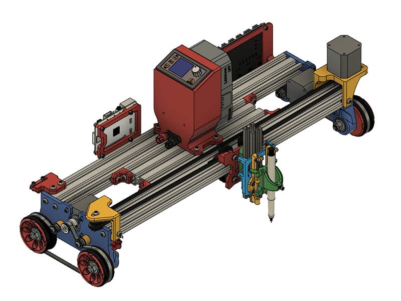
**Update 6/19/2020** I am currently redesigning the wheels & Wheel plate and adding spacers between bearings on the wheels. Also the bearing count will be 8 instead of 16 bearings since learning they are not necessary for the Wheel Plate. The spacers between the bearings in the wheels should solve my wheel binding problem. I will upload new files after printing & testing. **Update 4/19/2020** I added 2 new TPU tire models with tread. If you are using 3d Printed tires instead of the O-Rings, these should give a little more grip & if you add rubber bands to the wheels, these should help them stay on. The files are: **TPU_GrooveTread_Ring_FatBottom.stl** & **TPU_GrooveTread_Ring_FatTop.stl**. I am also redesigning the Carriage idler & motor Mount to give more printing width. The belt will probably need to be a little longer, so keep your belt a little longer if you are using current design & are interested in more printing width. This is what I call a Rolling Plotter that uses 2040 V-Slot for one axis and wheels with O-Rings & closed loop belt for the other axis. I wanted to be able to plot some drawings larger and couldn't find exactly what I wanted. The inspiration for this design comes mostly from a couple of machines similar on the openbuilds.com site. I wanted to use a little smaller wheels than the two machines on that site & started looking for the wheel size the lowrider CNC used on V1engineering.com site. I found https://www.thingiverse.com/thing:3826801 to give me the basic size of that wheel for a starting template. With the GT2 tooth gearing & O-Ring slots it doesn't look much like that now. The width of this machine is limited to the lengths of 2040 V-Slot you use. With 500mm lengths, I currently have about 370mm of travel along that axis. I have mine configured for the wheels to roll along the X-axis & the carriage rolls along the 2040 V-Slot is the Y-axis. I wanted it that way for the X-axis to be the longest. I have my maximum X Position set to 1000mm. The wheel distance could be more, but I haven't test accuracy on large drawings yet. The build log for this design can be found here: https://openbuilds.com/builds/a-rolling-plotter.9207/ You can find some more discussion about it here: https://forum.v1engineering.com/t/rolling-plotter-build/15389 dkj4linux is making a modified version of this design to use as a foam ripper. You can see his build log here: https://forum.v1engineering.com/t/lowrider-inspired-foam-ripper/8025/52 2 videos showing a couple of possibilities of this machine: Pen plot of 180mm diameter Flower of Life Pattern <iframe width="560" height="315" src="https://www.youtube.com/embed/IIjZrsuUH6U" frameborder="0" allow="accelerometer; autoplay; encrypted-media; gyroscope; picture-in-picture" allowfullscreen></iframe> That same pattern being carving in a pan of baking soda <iframe width="560" height="315" src="https://www.youtube.com/embed/d1lsTF1AyTY" frameborder="0" allow="accelerometer; autoplay; encrypted-media; gyroscope; picture-in-picture" allowfullscreen></iframe> This design uses a 444mm GT2 closed loop belt for the wheel drive. I experimented with different gearing also while waiting for the belts along with using a 3d printed TPU belt. The real belt works the best for me so far. I may play with the gearing version again after releasing these files. There is a BOM spreadsheet with links to suggested sites. I also included PDF build guide. The BOM & Build Guide are unverified, so with the metric hardware order a few extra if you don't have these on hand. 16 - 6082RS Bearings are used for the wheels & the Wheel Plate connections which are 22mm outer diameter. I built my rolling plotter using 22.5mm for bearings to fit in. There are 3 test prints for checking the size that best works for your printer. I only created STL files for the 22.5mm size which worked good for me. It also allows me to get those bearings out which I did a lot while testing this machine. If you want a different size or want to change part of the design, the included Fusion 360 Archive file **RollingPrinterComplete_Assembly_v4.f3z** you can edit to change it. I also included a sketchup file **RollingPrinterComplete_Assembly_v4.skp** for those that like sketchup or an easier way to view the assembly. The test print parts you want to print are: **BearingInsertTest_22_5.stl** **BearingInsertTest_22_4.stl** **BearingInsertTest_22_3.stl** The wheel bolts & O-Rings are the only non metric items in this build, but there are alternatives to what I used. For the Wheel mount bolts, you can use either 5/16"x2" bolts, 5/16" washer & lock nuts or M8 hardware. \#327 or #328 O-Rings are used for the tire tread as I have seen on some other designs. I used #327 as that is what I had, but #328 should be a better fit & not need to stretch as much to fit the wheel grooves. The wheels for these are: **Wheel_Plate_22_5_Rev8.stl** For that want to use metric O-Rings, the closest match should be: 4.5CSx47IDx56OD or 5.0CSx47IDx57OD but not tested For 4.5mm CS o-Rings use **4_5_mmCS_Oring_ShallowWheel_60mm_88T.stl** For 5.0mm CS O-Rings use **5_mmCS_Oring_ShallowWheel_60mm_88T.stl** The 4 idler bearings for the closed loop timing belt I used F695zz Mini Metal Double Shielded Flanged Ball Bearings as those worked best for me. It is a small space they are in, so you don't want them too big. You can try other types of ilder bearings, but these still moved freely even after tightening the M5 screws tight. For the electronics, I am using a MKS Gen 1.4 board with DRV8825 drivers and a spare Meanwell NES-350-12 P/S which is overkill for this machine. A 12v 6amp - 10 amp P/S should be sufficient. I am planning to eventually use https://www.thingiverse.com/thing:4226726 for a portable P/S. The 2 limit switch boards for the X & Y axis. There is no Z-axis, but a servo that controls the Pen Up/Pen Down. I am using Klipper firmware with octoprint running on a raspberry pi. I started off using Marlin, but couldn't get the servo to work in sync with the X/Y movement. Grbl firmware compatible boards are also an option with this plotter. I have only setup configuration files for Klipper & Marlin. If you make your own Z-axis with stepper motors, Marlin will work. For powering the raspberry pi instead of plugging into wall, I am using a ravpower usb charger that seems sufficient for my raspberry Pi 3b+. For the Z-axis with servo I am using this remix: https://www.thingiverse.com/thing:4276609 . There are also a couple of optional mounts with that design that use the 28BYJ-48 motor or a Nema17 pancake stepper motor. See that build for attaching that mount and additional parts you might need. The Parts to print are: 2 **Wheel_Plate_22_5_Rev8.stl** 4 **Oring_ShallowWheel_60mm_88T_22_5.stl** (Alternative to 3d print tires with TPU instead of buying the O-Rings) 8 **TPU_Tire.stl** 2 **GT2_218T_Belt.stl** (Print in TPU or purchase 2 - 144mm Length GT2 Belts) 1 **Carriage_IdlerPlate_Top.stl** 1 **Carriage_MotorMount_Top.stl** 4 **VSlot_Corner.stl** (or purchase aluminum or cast corners) 1 **Carriage_LimitSwitchBottomMount.stl** 1 **Wheel_LimitSwitchMount.stl** 1 **LimitSwitch_Spacer_4x.stl** 1 **6mmPlate_With_BeltClamp.stl** If you are using openbuilds Gantry Plate, you will need to also print 1 **Carriage_BeltConnect.stl** (Used with openbuilds Gantry Plate) 1 **Carriage_BeltConnect_M.stl** (Used with openbuilds Gantry Plate) 1 **RiPi3B_Mount_M.stl** (Optional parts if using MKS board & Meanwell P/S) 1 **M3_Spacer_4x.stl** 1 **MKS_V_Mount.stl** 1 **NES_350_V_Support.stl** All the parts above I printed with 4 Perimeters, .2mm Layer height & 50% infill with the exception of the limit switch mounts & electronics mounts I printed with 3 perimeter, .2mm Layer height & 20% infill with eSun PLA+. The TPU parts I printed using TPU from zyltech.com The klipper configuration file is in the zip file **RP_200411_Servo_Z_Dual_X.zip**. Extract file & change the file name to printer.cfg before uploading it to the raspberry Pi. Klipper Install Link on Github: https://github.com/KevinOConnor/klipper There are also some youtube videos of installing this. The Marlin configuration file is **Marlin-2.0.4.4.zip** With the Klipper firmware I redefined the G11 & G10 gcode to be Pen Up (G11) & Pen Down (G10). I edit the Gcode file by hand to change the file as I haven't found a better way to do this yet. If you are using Grbl this is probably an easier task, but I am not familiar with how that works. If you want to use Grbl firmware with this using an arduiono Uno or similar board, I would suggest looking at the guide with https://www.thingiverse.com/thing:2349232 drawing bot. There is a lot here & sure I missed something. Look over the BOM spreadsheet & build guide before printing any of this to make sure you can get all the parts you need.
With this file you will be able to print Rolling Plotter with lots of Possibilities with your 3D printer. Click on the button and save the file on your computer to work, edit or customize your design. You can also find more 3D designs for printers on Rolling Plotter with lots of Possibilities.